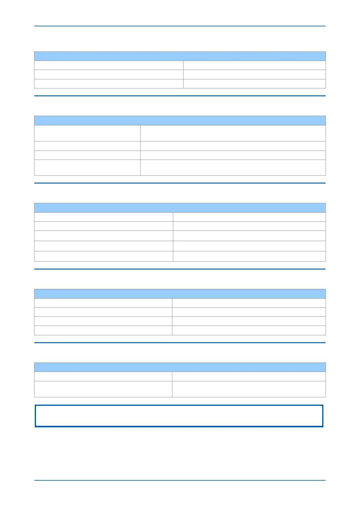
Test disturbance voltage 10 V rms
Test using AM 1 kHz @ 80%
Spot tests 27 MHz and 68 MHz
11.11 MAGNETIC FIELD IMMUNITY
Compliance
IEC 61000-4-8: 2009 Level 5
IEC 61000-4-9/10: 2001 Lev
el 5
IEC 61000-4-8 test 100 A/m applied continuously, 1000 A/m applied for 3 s
IEC 61000-4-9 test 1000 A/m applied in all planes
IEC 61000-4-10 test
100 A/m applied in all planes at 100 kHz/1 MHz with a burst duration of 2
seconds
11.12 CONDUCTED EMISSIONS
Compliance EN 55022: 2010, IEC 60255-26:2013
Power supply test 1 0.15 - 0.5 MHz, 79 dBµV (quasi peak) 66 dBµV (average)
Power supply test 2 0.5 – 30 MHz, 73 dBµV (quasi peak) 60 dBµV (average)
RJ45 test 1 (where applicable) 0.15 - 0.5 MHz, 97 dBµV (quasi peak) 84 dBµV (average)
RJ45 test 2 (where applicable) 0.5 – 30 MHz, 87 dBµV (quasi peak) 74 dBµV (average)
11.13 RADIATED EMISSIONS
Compliance EN 55022: 2010, IEC 60255-26:2013
Test 1 30 – 230 MHz, 40 dBµV/m at 10 m measurement distance
Test 2 230 – 1 GHz, 47 dBµV/m at 10 m measurement distance
Test 3 1 – 2 GHz, 76 dBµV/m at 10 m measurement distance
11.14 POWER FREQUENCY
Compliance IEC 60255-22-7:2003, IEC 60255-26:2013
Opto-inputs (Compliance is achieved using the opto-input
filter)
300 V common-mode (Class A)
150 V differential mode (Class A)
Note:
Compliance is achieved using the opto-input filter.
P54A/B/C/E Chapter 22 - Technical Specifications
P54xMED-TM-EN-1 529
 Loading...


