6.5.3 INPUT BOARD
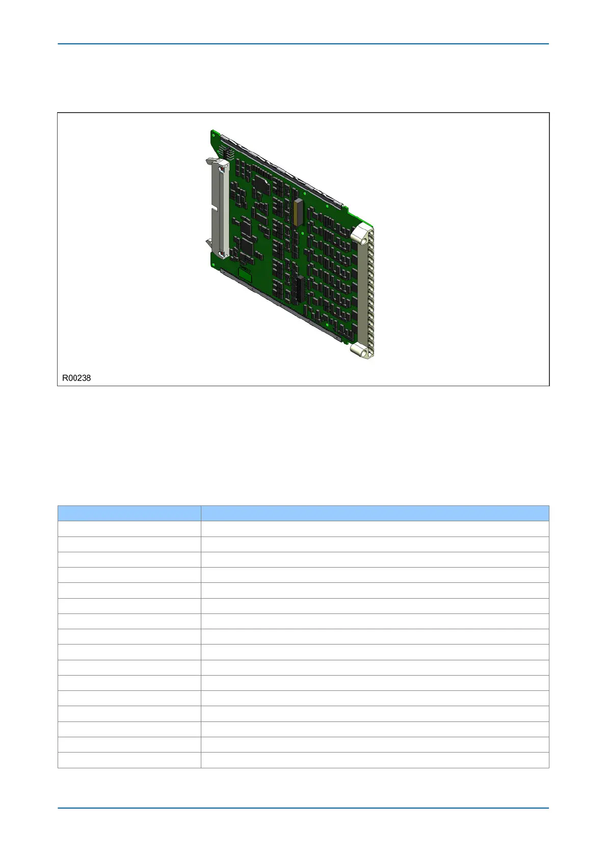
Figure 19: Input board
The input boar
d is used to convert the analogue signals delivered by the current and voltage transformers into
digital quantities used by the IED. This input board also has on-board opto-input circuitry, providing eight optically-
isolated digital inputs and associated noise filtering and buffering. These opto-inputs are presented to the user by
means of a MD terminal block, which sits adjacent to the analogue inputs HD terminal block.
The input board is connected physically and electrically to the transformer board to form a complete input module.
The terminal numbers of the opto-inputs are as follows:
Terminal Number Opto-input
Terminal 1 Opto 1 -ve
Terminal 2 Opto 1 +ve
Terminal 3 Opto 2 -ve
Terminal 4 Opto 2 +ve
Terminal 5 Opto 3 -ve
Terminal 6 Opto 3 +ve
Terminal 7 Opto 4 -ve
Terminal 8 Opto 4 +ve
Terminal 9 Opto 5 -ve
Terminal 10 Opto 5 +ve
Terminal 11 Opto 6 -ve
Terminal 12 Opto 6 +ve
Terminal 13 Opto 7 –ve
Terminal 14 Opto 7 +ve
Terminal 15 Opto 8 –ve
Terminal 16 Opto 8 +ve
Chapter 3 - Hardware Design P54A/B/C/E
50 P54xMED-TM-EN-1
 Loading...


