3.2.1 EIA(RS)485 BIASING REQUIREMENTS
Biasing requires that the signal lines be weakly pulled to a defined voltage level of about 1 V. There should only be
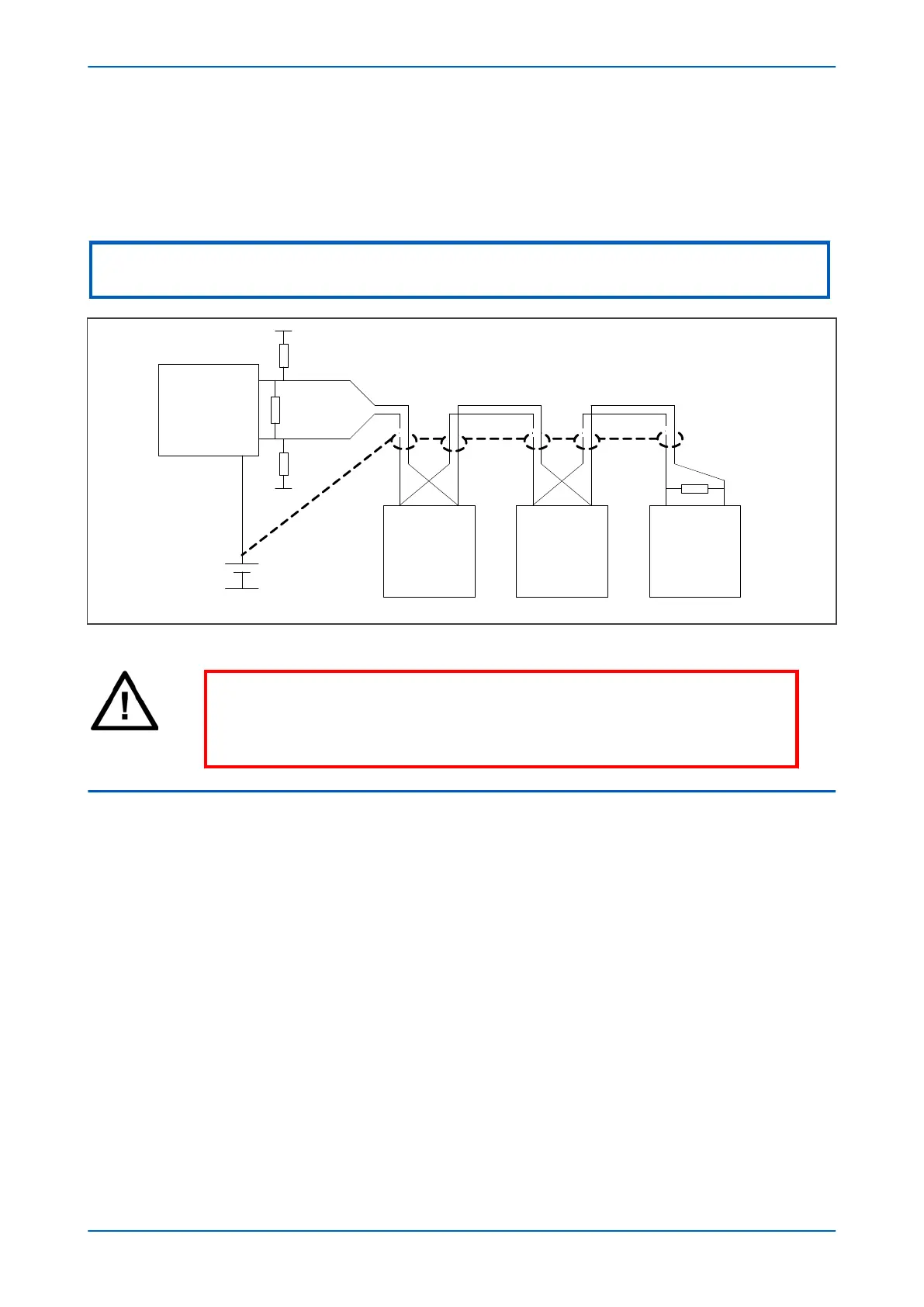
one bias point on the bus, which is best situated at the master connection point
. The DC source used for the bias
must be clean to prevent noise being injected.
Note:
Some devices may be able to provide the bus bias, in which case external components would not be required.
V01000
Master
6 – 9 V DC
0
V
120 Ω
180 Ω bias
180 Ω bias
Slave Slave Slave
120 Ω
Figure 169: RS485 biasing circuit
Warning:
It is extr
emely important that the 120 Ω termination resistors are fitted. Otherwise
the bias voltage may be excessive and may damage the devices connected to the
bus.
3.3 K-BUS
K-Bus is a robust signalling method based on RS485 voltage levels. K-Bus incorporates message framing, based on
a 64
kbps synchronous HDLC protocol with FM0 modulation to increase speed and security.
The rear interface is used to provide a permanent connection for K-Bus, which allows multi-drop connection.
A K-Bus spur consists of up to 32 IEDs connected together in a multi-drop arrangement using twisted pair wiring.
The K-Bus twisted pair connection is non-polarised.
It is not possible to use a standard EIA(RS)232 to EIA(RS)485 converter to convert IEC 60870-5 FT1.2 frames to K-
Bus. A protocol converter, namely the KITZ101, KITZ102 or KITZ201, must be used for this purpose. Please consult
General Electric for information regarding the specification and supply of KITZ devices. The following figure
demonstrates a typical K-Bus connection.
Chapter 17 - Communications P54A/B/C/E
346 P54xMED-TM-EN-1
 Loading...


