6 HIGH IMPEDANCE REF
The device provides a high impedance restricted earth fault protection function. An external resistor is required to
pr
ovide stability in the presence of saturated line current transformers. Current transformer supervision signals do
not block the high impedance REF protection. The appropriate logic must be configured in PSL to block the high
impedance REF when any of the above signals is asserted.
6.1 HIGH IMPEDANCE REF PRINCIPLE
This scheme is very sensitive and can protect against low levels of fault current, typical of winding faults.
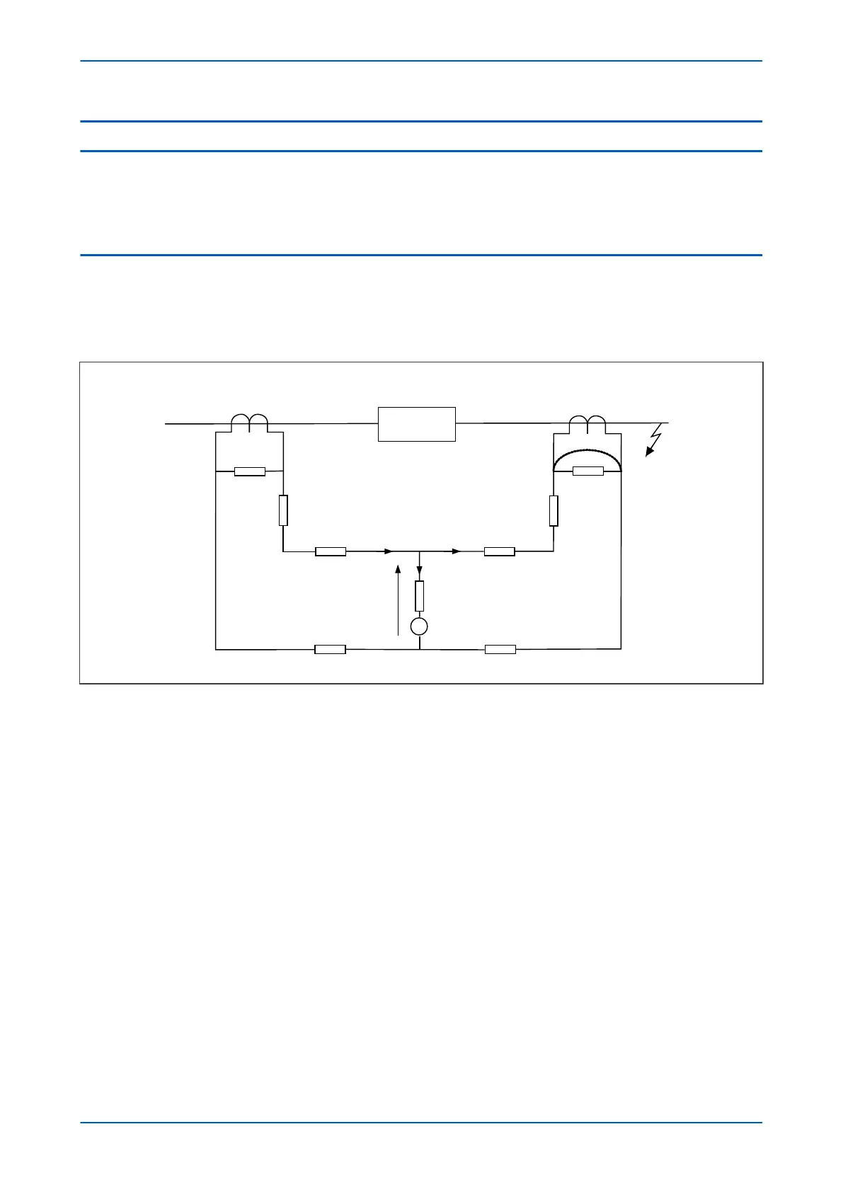
High Impedance REF pr
otection is based on the differential principle. It works on the circulating current principle as
shown in the following diagram.
V00671
R
Z
m
1
R
CT1
R
L1
Z
m2
V
s
R
CT2
R
L3
I
F
I
S
R
L4
R
L2
Healthy CT
Saturated CT
A-G
Protected
circuit
I
R
S
T
I = I
s
+ I
F
Figure 107: High Impedance REF principle
When subjected to heavy thr
ough faults the line current transformer may enter saturation unevenly, resulting in
imbalance. To ensure stability under these conditions a series connected external resistor is required, so that most
of the unbalanced current will flow through the saturated CT. As a result, the current flowing through the device
will be less than the setting, therefore maintaining stability during external faults.
Voltage across REF element V
s
= I
F
(R
CT2
+ R
L3
+ R
L4
)
Stabilising resistor R
ST
= V
s
/I
s
–R
R
where:
● I
F
= maximum secondary through fault current
● R
R
= device burden
● R
CT
= CT secondary winding resistance
● R
L2
and R
L3
= Resistances of leads from the device to the current transformer
● R
ST
= Stabilising resistor
High Impedance REF can be used for either delta windings or star windings in both solidly grounded and
resistance grounded systems. The connection to a modern IED are as follows:
Chapter 9 - Current Protection Functions P54A/B/C/E
212 P54xMED-TM-EN-1
 Loading...


