10 CURRENT DIFFERENTIAL PROTECTION
10.1 CURRENT DIFFERENTIAL BIAS CHARACTERISTIC
1. In the C
ONFIGURATION column, disable all protection elements other than the one being tested.
2. Make a note of which elements need to be re-enabled after testing.
3. Set the device to loopback mode, isolating it from the remote end.
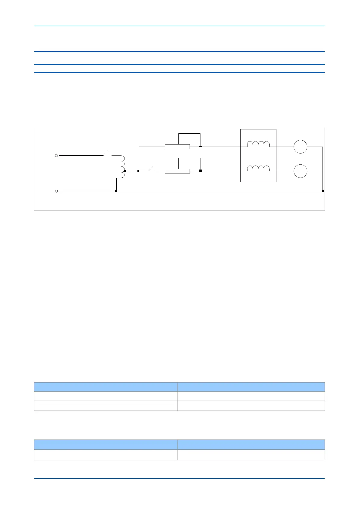
4. Connect the test circuit shown below. Alternatively, use an injection test set to supply Ia and Ib
V01452
Ra
Rb
P54x IED
Ph a
Ph b
Ia
Ib
A
A
L
N
Figure 206: Current Differential Bias Characteristics
10.1.1 LOWER SLOPE
If three LEDs have been assigned to provide phase segregated trip information (Trip A, Trip B and Trip C), these may
be used to indicate corr
ect operation per-phase. If LEDs are not used, use monitor options, as follows.
1. Go to COMMISSION TESTS > Monitor Bit. Change cells 1, 2 and 3 to the values 523, 524 and 525 respectively.
The Test Port Status cell then displays the status of Trip Output A (DDB 523), Trip Output B (DDB 524) and
Trip Output C (DDB 525), with the rightmost bit representing Phase A Trip. From now on monitor the Test
Port Status cell.
2. Make sure that the IED is in loopback mode by setting the Loopback Mode cell to External and applying a
loop-back, either by direct fibre or using a P59x. Alternatively you can set the Test Loopback cell to
Internal.
3. Adjust the variac and the resistor to give a bias current of 1pu in the A-phase (1A into terminals 3-2 for 1A
applications, or 5A into terminals 1-2 for 5A applications).
The device trips, contacts associated with the A-phase operate, and bit 1 (rightmost) of the Test Port Status
cell is set to 1. Some LEDs, including the yellow alarm LED, switch OFF, but ignore these for the moment.
4. When the current in the A Phase is established, close the switch and slowly increase the current in the B
phase from zero until Phase B trips (bit 2 of the Test Port Status cell is set to 1).
For the initial conditions where the magnitude of the bias current in phase A = 1 pu, record the phase B current
magnitude and check that it corresponds to the following.
Connection type Magnitude of differential current in phase B
2-terminal & dual redundant 0.25 pu +/-10%
3-terminal 0.216 pu +/-10%
Assumption: Is1 = 0.2 pu, k1 = 30%, Is2 = 2.0 pu
For other differ
ential settings or current injected into A phase (Ia), the following formula can be used (enter slope in
pu form, which is. percentage/100):
Connection type Magnitude of differential current in phase B
2-terminal & dual redundant 0.5 x (Is1 + (Ia x k1)) pu +/- 10%
P54A/B/C/E Chapter 20 - Commissioning Instructions
P54xMED-TM-EN-1 475
 Loading...


