7.3 THERMAL OVERLOAD PROTECTION IMPLEMENTATION
The device incorporates a current-based thermal characteristic, using RMS load current to model heating and
cooling of the pr
otected plant. The element can be set with both alarm and trip stages.
Thermal Overload Protection is implemented in the THERMAL OVERLOAD column of the relevant settings group.
This column contains the settings for the characteristic type, the alarm and trip thresholds and the time constants.
7.4 THERMAL OVERLOAD PROTECTION LOGIC
IC
IB
IA
IB
IC
Reset Thermal
Thermal Trip
Thermal
Calculation
Thermal Trip
Thermal Alarm
Thermal State
Characteristic
Single
Disabled
Dual
Time Constant 1
Time Constant 2
Max RMS
Thermal trip
threshold
Thermal Alarm
V00630
IA
680
785
445
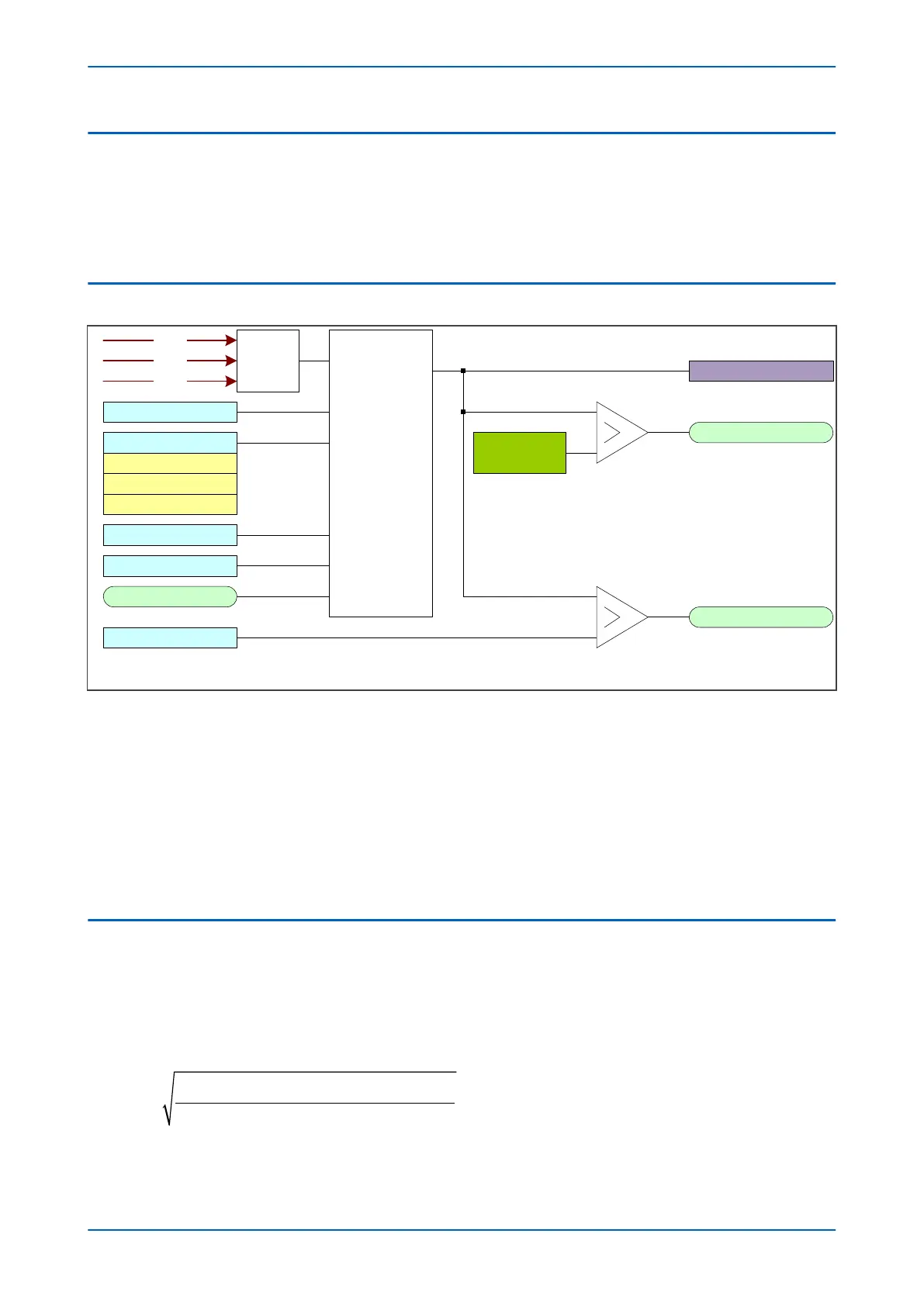
Figure 109: Thermal overload protection logic diagram
The magnitudes of the thr
ee phase input currents are compared and the largest magnitude is taken as the input
to the thermal overload function. If this current exceeds the thermal trip threshold setting a start condition is
asserted.
The Start signal is applied to the chosen thermal characteristic module, which has three outputs signals; alarm trip
and thermal state measurement. The thermal state measurement is made available in one of the MEASUREMENTS
columns.
The thermal state can be reset by either an opto-input (if assigned to this function using the programmable
scheme logic) or the HMI panel menu.
7.5 APPLICATION NOTES
7.5.1 SETTING GUIDELINES FOR DUAL TIME CONSTANT CHARACTERISTIC
The easiest way of solving the dual time constant thermal equation is to express the current in terms of time and
to use a spreadsheet to calculate the current for a series of increasing operating times using the following
equation, then plotting a graph.
I
I e I e k I
e e
p
t
p
t
FLC
t
=
+ −
+
−
( )
−
( )
−
( )
0 4 0 6
0 4 0 6
2
1
2
2
2 2
1
. . . . .
. .
/ /
/
τ τ
τ
−−
( )
−
t/
τ
2
1
P54A/B/C/E Chapter 9 - Current Protection Functions
P54xMED-TM-EN-1 215
 Loading...


