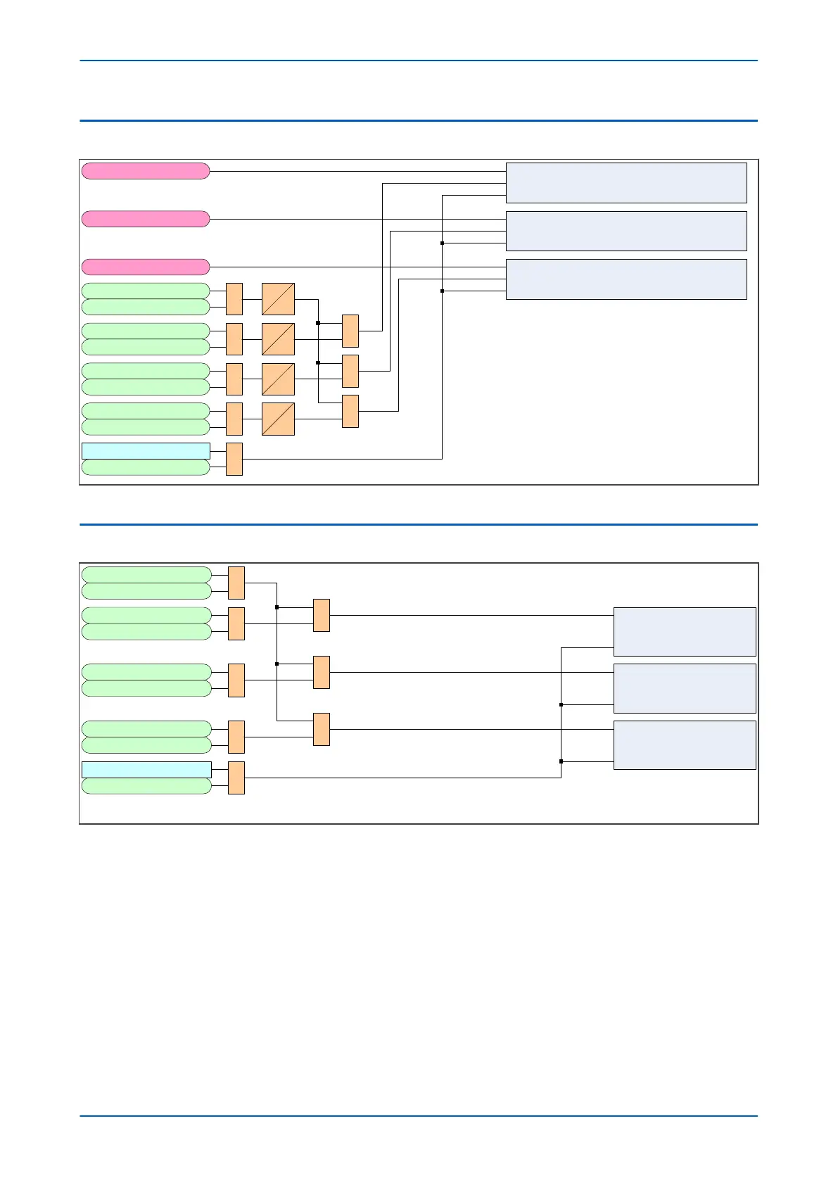
5.1 BROKEN CURRENT ACCUMULATOR
V01272
Set Cumulative IA broken InSet
Reset
PhaseACurrent
Set Cumulative IB broken InSet
Reset
PhaseBCurrent
Set Cumulative IC broken InSet
Reset
PhaseCCurrent
Trip 3ph
1
External Trip3 ph 0
t
Trip Output A
1
External Trip A
0
t
Trip Output B
1
External Trip B 0
t
Trip Output C
1
External Trip C 0
t
Note: All timers have 1 cycle pickup delay
1
1
1
1
Reset CB Data
Reset CB Data
Note: Broken current totals not incremented when device is in test mode
Figure 122: Broken Current Accumulator logic diagram
5.2 CB TRIP COUNTER
1
V01276
Trip 3ph
External Trip3ph
Trip Output A
External Trip A
Trip Output B
External Trip B
Trip Output C
External Trip C
Reset CB Data
Reset CB Data
1
1
1
1
1
1
1
Phase A Trip Counter
Increment
Reset
Phase B Trip Counter
Increment
Reset
Phase C Trip Counter
Increment
Reset
Figure 123: CB Trip Counter logic diagram
P54A/B/C/E Chapter 12 - Monitoring and Control
P54xMED-TM-EN-1 253
 Loading...


