8 BROKEN CONDUCTOR PROTECTION
One type of unbalanced fault is the 'Series' or 'Open Circuit' fault. This type of fault can arise from, among other
things, br
oken conductors. Series faults do not cause an increase in phase current and so cannot be detected by
overcurrent protection. However, they do produce an imbalance, resulting in negative phase sequence current,
which can be detected.
It is possible to apply a negative phase sequence overcurrent element to detect broken conductors. However, on a
lightly loaded line, the negative sequence current resulting from a series fault condition may be very close to, or
less than, the full load steady state imbalance arising from CT errors and load imbalances, making it very difficult
to distinguish. A regular negative sequence element would therefore not work at low load levels. To overcome this,
the device incorporates a special Broken Conductor protection element.
The Broken Conductor element measures the ratio of negative to positive phase sequence current (I2/I1). This ratio
is approximately constant with variations in load current, therefore making it more sensitive to series faults than
standard negative sequence protection.
8.1 BROKEN CONDUCTOR PROTECTION IMPLEMENTATION
Broken Conductor protection is implemented in the BR
OKEN CONDUCTOR column of the relevant settings group.
This column contains the settings to enable the function, for the pickup threshold and the time delay.
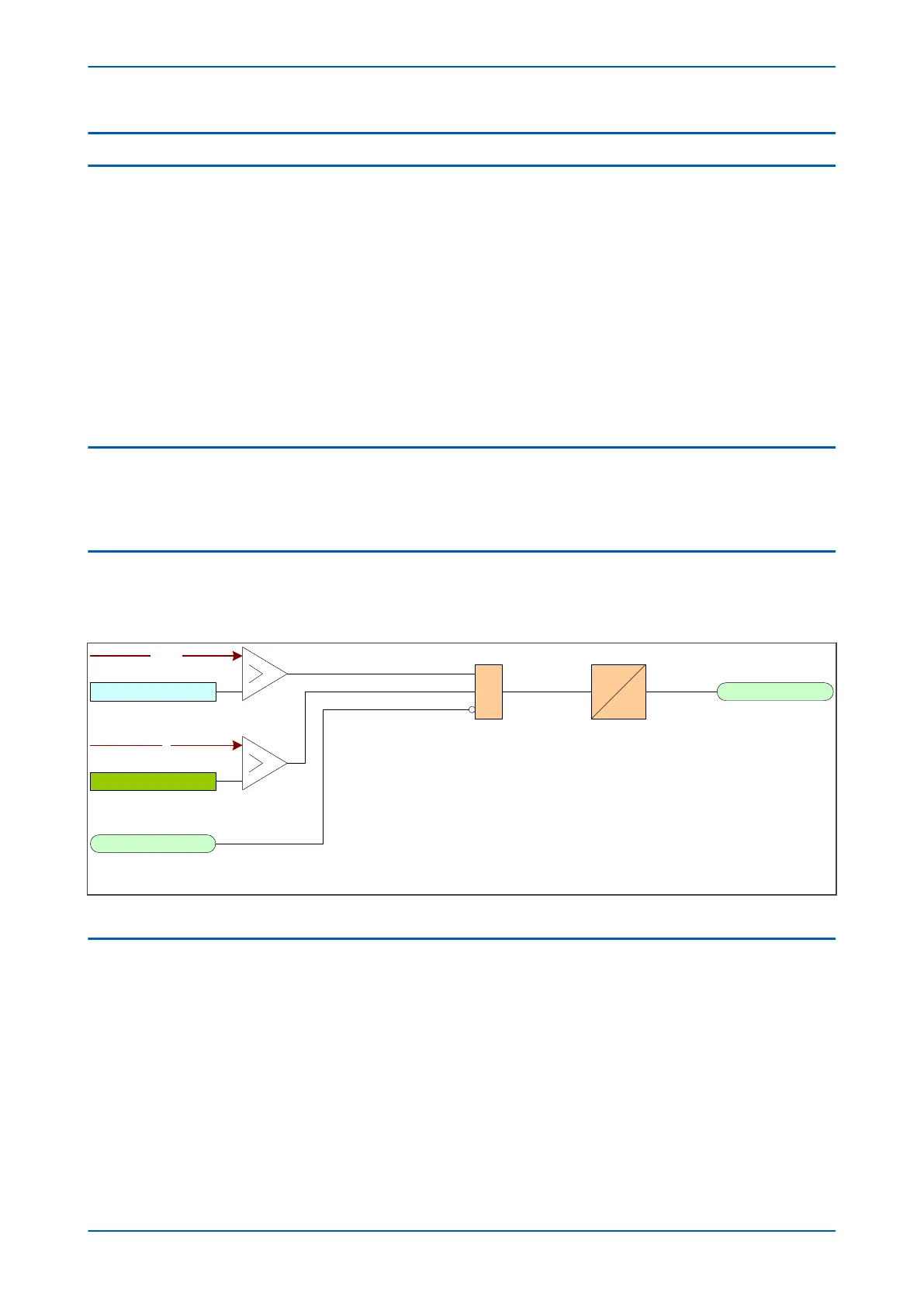
8.2 BROKEN CONDUCTOR PROTECTION LOGIC
The ratio of I
2
/I
1
is calculated and compar
ed with the threshold setting. If the threshold is exceeded, the delay
timer is initiated. The CTS block signal is used to block the operation of the delay timer.
CTS Block
Broken Wire Trip
V00739
I2/I1
I2/I1 Setting
&
I2
Low Current
928
679
Figure 112: Broken conductor logic
8.3 APPLICATION NOTES
8.3.1 SETTING GUIDELINES
For a broken conductor affecting a single point earthed power system, there will be little zero sequence current
flow and the ratio of I
2
/I
1
that flows in the pr
otected circuit will approach 100%. In the case of a multiple earthed
power system (assuming equal impedance’s in each sequence network), the ratio I
2
/I
1
will be 50%.
In practise, the levels of standing negative phase sequence current present on the system govern this minimum
setting. This can be determined from a system study, or by making use of the measurement facilities at the
commissioning stage. If the latter method is adopted, it is important to take the measurements during maximum
system load conditions, to ensure that all single-phase loads are accounted for.
P54A/B/C/E Chapter 9 - Current Protection Functions
P54xMED-TM-EN-1 219
 Loading...


