6 CT COMPENSATION
The primary and secondary ratios for the phase current transformers are set in the C
T AND VT RATIOS column.
These settings are used to display the phase current quantities in the MEASUREMENTS 1 column. The device can
be set to display the input current either in primary values or in secondary values.
To ensure correct operation of the differential elements, it is important that under load and through fault
conditions, the currents into the differential elements of the devices balance. If the CTs have different ratios this will
not be the case. This product has CT ratio correction (magnitude compensation) to overcome this problem.
When calculating differential and bias currents, the devices use per-unit (p.u.) quantities. CT ratio compensation is
used to scale-up the current signals to match those of the remote terminals by setting an appropriate value in the
Ph CT Corr'tion setting in the CURRENT DIFF column. Because of dynamic limitations, this scaled-up value is
limited to 40 p.u. Values exceeding this are clipped at 40 p.u.
Similarly compensated per-unit values are used in the calculation of the differential and bias currents.
The per-unit compensated values of local and remote currents as well as the per-unit values of differential and
bias currents are scaled-down by the local CT ratio correction factor and displayed in the MEASUREMENTS 3
column.
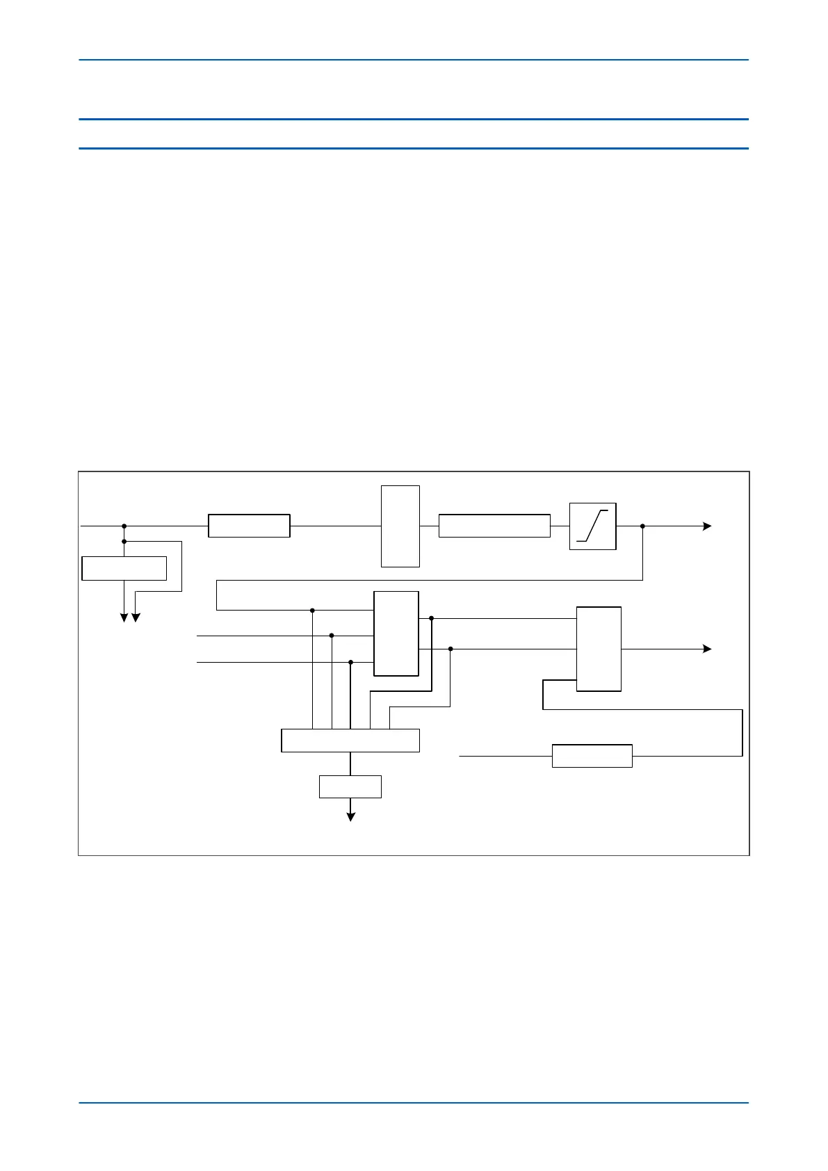
The process is outlined in the figure below:
D
i
f
f
/
B
i
a
s
c
a
l
c
u
l
a
t
i
o
n
s
* CT_Ratio
V
e
c
t
o
r
c
o
r
r
e
c
t
i
o
n
M
e
a
s
u
r
e
m
e
n
t
s
1
[Amps sec.]
* 1 / I
CT rated
[p.u.]
T
r
a
n
s
m
i
s
s
i
o
n
t
o
R
e
m
o
t
e
e
n
d
[p.u.]
Secondary CT
rating
* 1 / CT_Correction
* I
CT rated
Primary or
Secondary CT
rating
Measurements 3
T
r
i
p
D
e
c
i
s
i
o
n
* 1 / I
CT rated
Settings
[Amps pri. or sec.]
Primary or
Secondary CT
rating
Settings [p.u.]
Trip, Intertrip
40 p.u. clipping
V02609
Figure 42: CT Compensation
Chapter 6 - Current Differential Protection P54A/B/C/E
112 P54xMED-TM-EN-1
 Loading...


