2.2.2 OVERFREQUENCY PROTECTION LOGIC
F>1 TripF>1 Trip
F>1 StatusF>1 Status
V00862
DT
F>1 StartF>1 Start
&
EnabledEnabled
F>1 SettingF>1 Setting
Freq Not FoundFreq Not Found
Averaging
F>1 Timer BlockF>1 Timer Block
All Poles DeadAll Poles Dead
1
FreqFreq
890
1370
1153
1159
1165
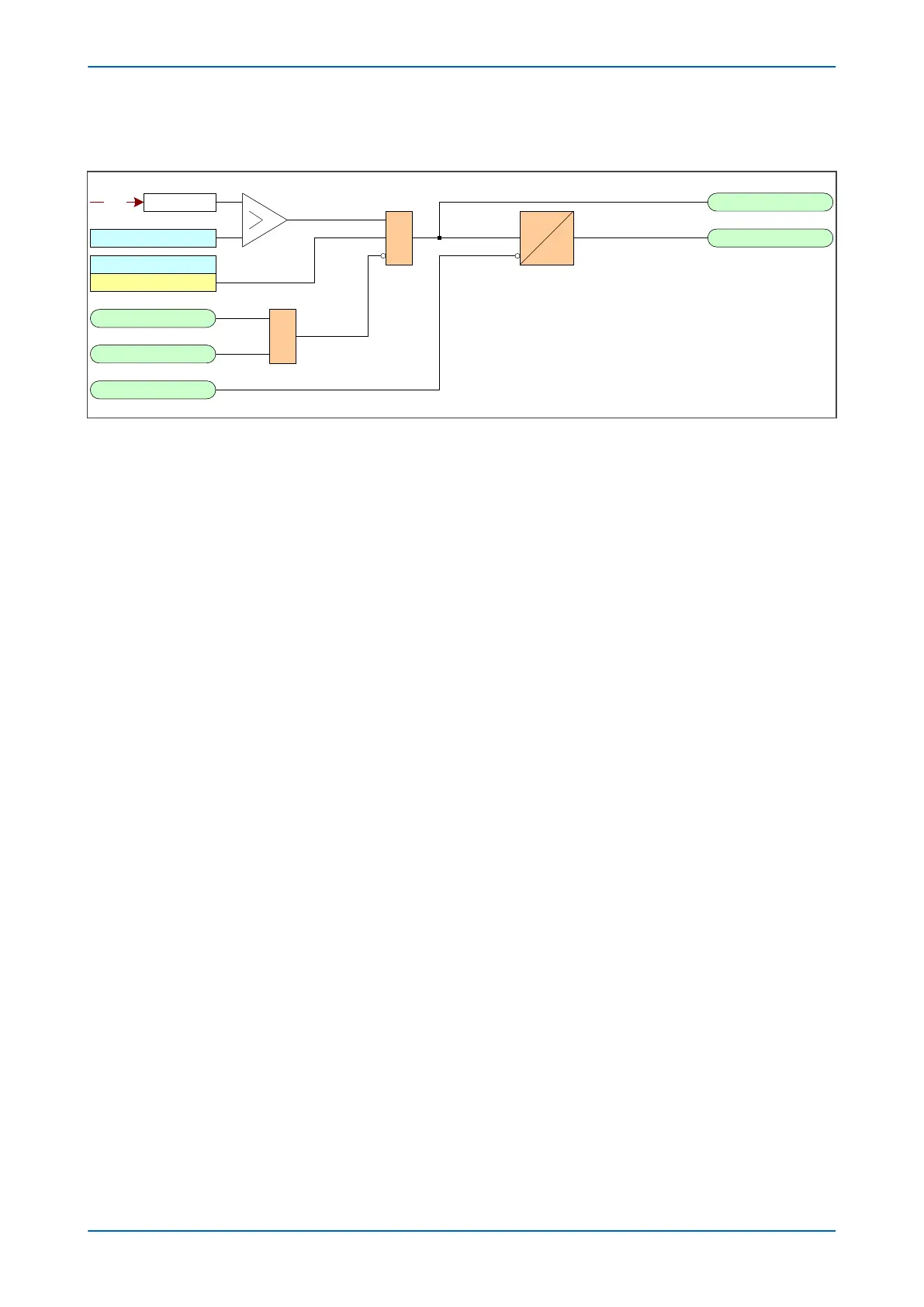
Figure 119: Overfrequency logic (single stage)
If the fr
equency is above the setting and not blocked, the DT timer is started and after this has timed out, the trip is
produced. If the frequency cannot be determined, the function is blocked.
2.2.3 APPLICATION NOTES
2.2.3.1 SETTING GUIDELINES
Following changes on the network caused by faults or other operational requirements, it is possible that various
subsystems will be formed within the pow
er network. It is likely that these subsystems will suffer from a
generation/load imbalance. The "islands" where generation exceeds the existing load will be subject to
overfrequency conditions. Severe over frequency conditions may be unacceptable to many industrial loads, since
running speeds of motors will be affected. The overfrequency element can be suitably set to sense this
contingency.
Chapter 11 - Frequency Protection Functions P54A/B/C/E
240 P54xMED-TM-EN-1
 Loading...


