5.1.5 WATCHDOG CONTACTS
Using a continuity tester, check that the Watchdog contacts are in the following states:
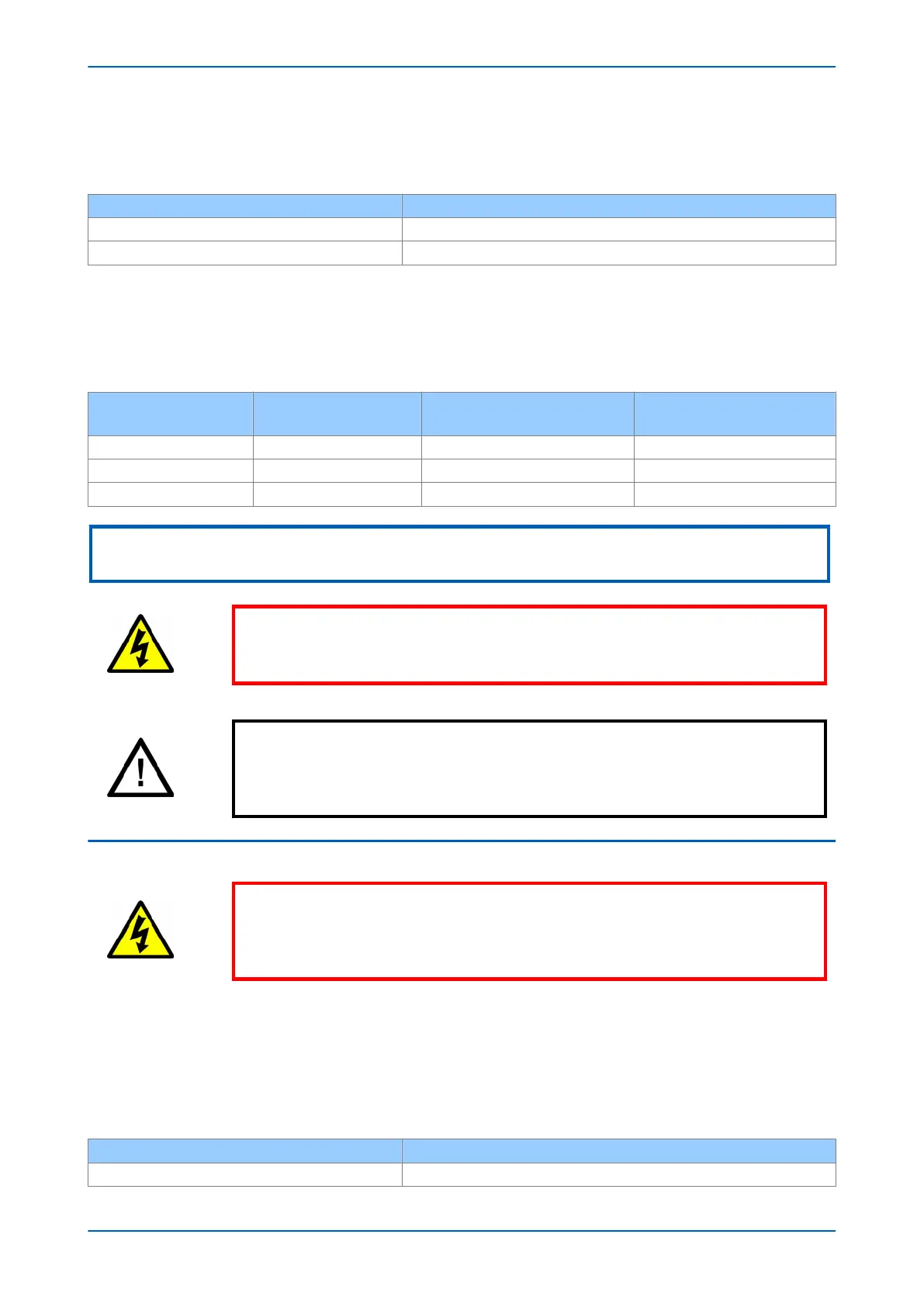
Terminals Contact state with product de-energised
11 - 12 on power supply board Closed
13 - 14 on power supply board Open
5.1.6 POWER SUPPLY
Depending on its nominal supply rating, the IED can be operated from either a DC only or an AC/DC auxiliary
supply. The incoming v
oltage must be within the operating range specified below.
Without energising the IED measure the auxiliary supply to ensure it is within the operating range.
Nominal supply rating
DC
Nominal supply rating
A
C RMS
DC operating range AC operating range
24 - 54 V N/A 19 to 65 V N/A
48 - 125 V 30 - 100 V 37 to 150 V 24 - 110 V
110 - 250 V 100 - 240 V 87 to 300 V 80 to 265 V
Note:
The IED can withstand an AC ripple of up to 12% of the upper rated voltage on the DC auxiliary supply.
Warning:
Do not energise the IED or interface unit using the battery charger with the battery
disconnected as this can irreparably damage the power supply circuitry.
Caution:
Ener
gise the IED only if the auxiliary supply is within the specified operating ranges.
If a test block is provided, it may be necessary to link across the front of the test plug
to connect the auxiliary supply to the IED.
5.2 PRODUCT CHECKS WITH THE IED ENERGISED
Warning:
The curr
ent and voltage transformer connections must remain isolated from the IED
for these checks. The trip circuit should also remain isolated to prevent accidental
operation of the associated circuit breaker.
The following group of tests verifies that the IED hardware and software is functioning correctly and should be
carried out with the supply applied to the IED
.
5.2.1 WATCHDOG CONTACTS
Using a continuity tester, check that the Watchdog contacts are in the following states when energised and
healthy.
Terminals Contact state with product energised
11 - 12 on power supply board Open
P54A/B/C/E Chapter 20 - Commissioning Instructions
P54xMED-TM-EN-1 457
 Loading...


