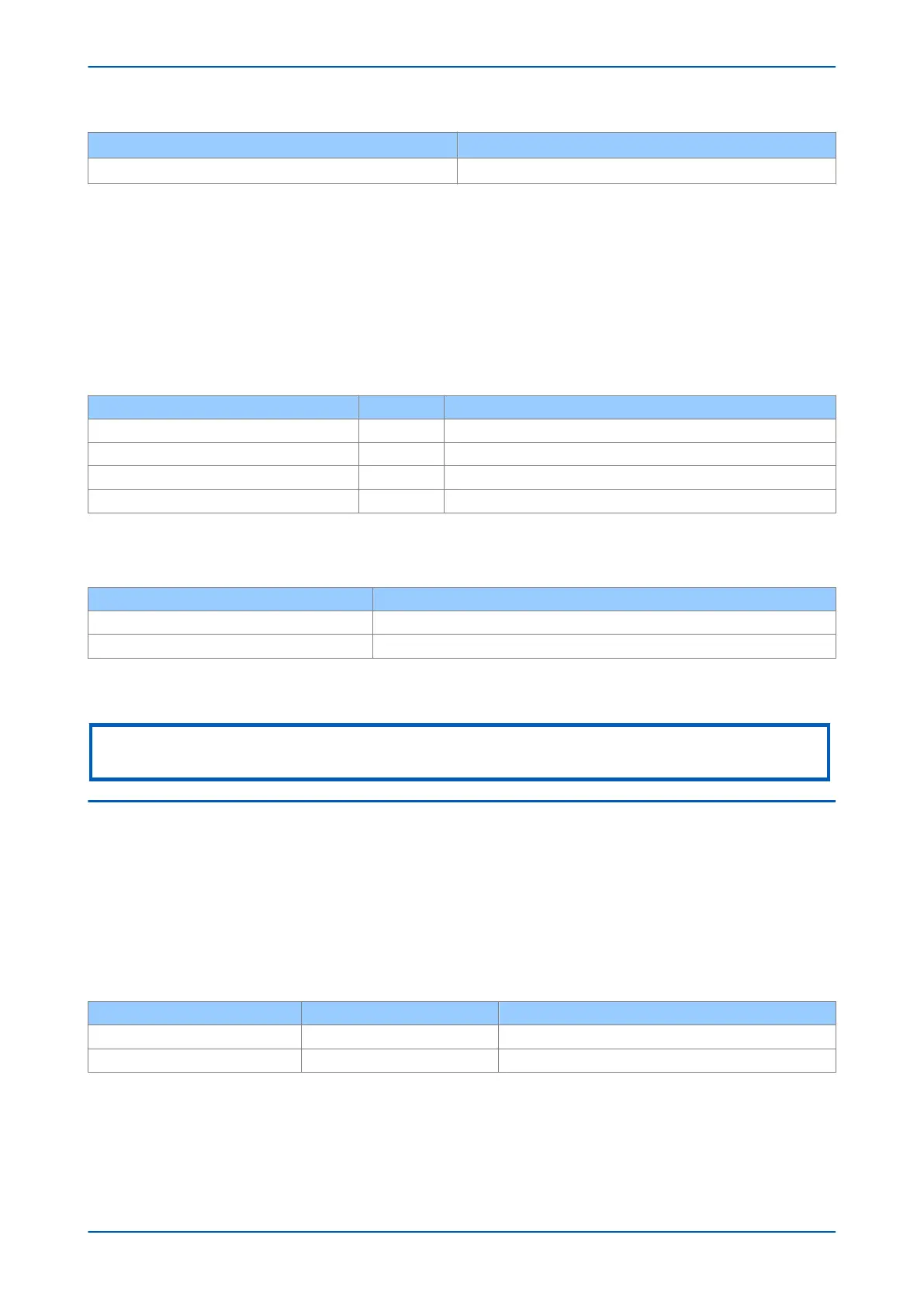
Connection type Magnitude of differential current in phase B
3-terminal 0.333 x (Is1 + (1.5 x Ia x k1)) pu +/- 10
Assumption: Ia < Is2
S
witch OFF the AC supply, read and clear all alarms.
10.1.2 UPPER SLOPE
1. Repeat the lower slope test but with the bias current set in the A-phase to 3 pu.
2.
When the current in the A Phase is established, close the switch and slowly increase the current in the B
phase from zero until phase B trips (bit 2 of the Test Port Status cell is set to 1).
For the initial conditions where the magnitude of the bias current in phase A = 3 pu, record the phase B current
magnitude and check that it corresponds to the information below.
Connection type k2 Magnitude of differential current in phase B
2-terminal & dual redundant 150% 1.15 pu +/- 10%
2-terminal & dual redundant 100% 0.9 pu +/- 10%
3-terminal 150% 1.51 pu +/- 10%
3-terminal 100% 1.1 pu +/- 10%
Assumption: Is1 = 0.2 pu, k1 = 30%, Is2 = 2.0 pu, k2 as above
For other differ
ential settings or current injected into A phase (Ia), the formula below can be used (enter slopes in
pu form, which is percentage/100):
Connection type Magnitude of differential current in phase B
2-terminal & dual redundant 0.5 x [(Ia x k2) – {(k2 – k1) x Is2\- } + Is1] pu +/- 20%
3-terminal 0.333 x [(1.5 x Ia x k2) – {(k2 – k1) x Is2\- } + Is1] pu +/- 20%
Assumption: Ia > IS2
S
witch OFF the ac supply and reset the alarms.
Note:
For 5 A applications, keep the duration of current injections short to avoid overheating of the variac or injection test set
10.2 CURRENT DIFFERENTIAL OPERATION AND CONTACT ASSIGNMENT
Phase A
1.
Retaining the same test circuit as before, prepare for an instantaneous injection of 3 pu current in the A
phase, with no current in the B phase (B phase switch open).
2. Set a timer to start when the fault injection is applied, and to stop when the trip occurs.
3. To verify the correct output contact mapping, use the trip contacts that would be expected to trip the circuit
breaker(s), as shown below. For two breaker applications, stop the timer once both CB1 and CB2 trip
contacts have closed. This can be achieved by connecting the contacts in series to stop the timer.
Single breaker Two circuit breakers
Three Pole Tripping Any Trip Any Trip (CB1) and Any Trip (CB2)
Single Pole Tripping Trip A Trip A (CB1) and Trip A (CB2)
Chapter 20 - Commissioning Instructions P54A/B/C/E
476 P54xMED-TM-EN-1
 Loading...


