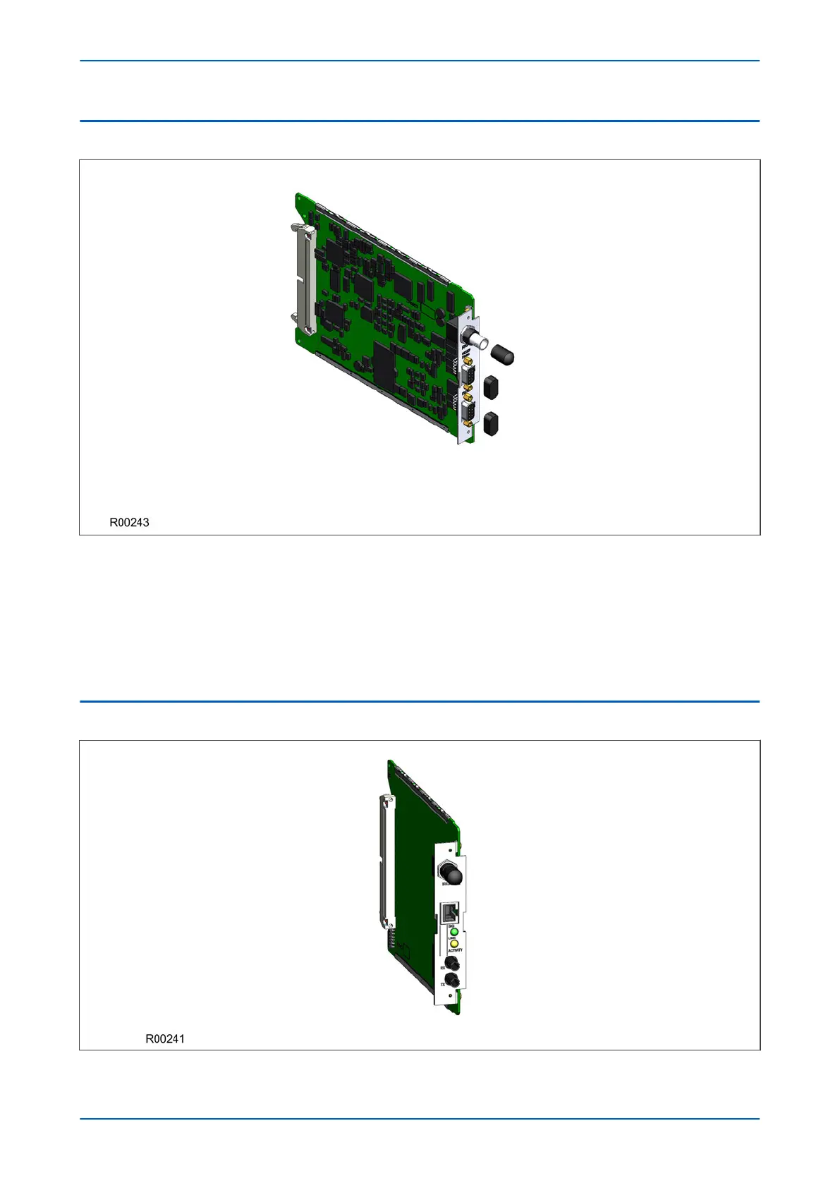
6.9 REAR COMMUNICATION BOARD
Figure 23: Rear communication board
The optional communications boar
d containing the secondary communication ports provide two serial interfaces
presented on 9 pin D-type connectors. These interfaces are known as SK4 and SK5. Both connectors are female
connectors, but are configured as DTE ports. This means pin 2 is used to transmit information and pin 3 to receive.
SK4 can be used with RS232, RS485 and K-bus. SK5 can only be used with RS232 and is used for electrical
teleprotection. The optional rear communications board and IRIG-B board are mutually exclusive since they use
the same hardware slot. However, the board comes in two varieties; one with an IRIG-B input and one without.
6.10 ETHERNET BOARD
Figure 24: Ethernet board
Chapter 3 - Hardware Design P54A/B/C/E
54 P54xMED-TM-EN-1
 Loading...


