D
IRECTION FR091521, REVISION 1 VIVID S60N/VIVID S70N BASIC SERVICE MANUAL
8-52 Section 8-3 - Control Console Components - Replacement Procedures
PRELIMINARY
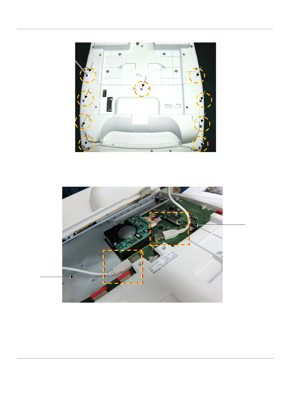
3.) Loosen and remove the 9 Phillips screws that secure the bottom cover in place - see Figure 8-58
4.) Gently lift the bottom cover (see note below) and disconnect the two USB cables from the side of
the trackball, as shown in Figure 8-59 (see additional note below).
Note: For systems previously fitted with the Alphanumeric Keyboard option, the AN Keyboard is
attached to the bottom cover (integral part).
Note: For systems without the Alphanumeric Keyboard option currently installed, there is only
one USB cable connected.
Figure 8-58 Operator Panel Keyboard Assembly - Bottom Cover Securing Screws
Figure 8-59 Location of USB Cables

 Loading...


