D
IRECTION FR091521, REVISION 1 VIVID S60N/VIVID S70N BASIC SERVICE MANUAL
Chapter 8 - Replacement Procedures 8-169
PRELIMINARY
3.) Lead the cables via the right cable hook (Figure 8-203) and make one or two loops to shorten the
cable.
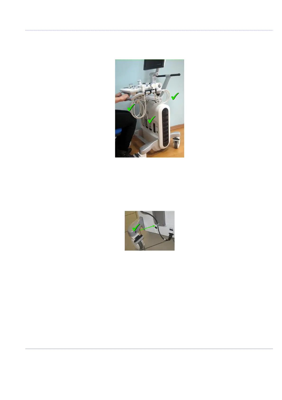
4.) Insert the probe in the probe holder as shown in Figure 8-205.
NOTE: Image for illustration purposes only (pending update).
5.) Similarly, route the left probe cable/s via the cable holder and the left cable hook.
6.) Route the AC power cable via the AC Power Cable hook and lead it upwards as shown in
Figure 8-206.
NOTE: Whenever moving the Vivid™ S60/Vivid™ S70 scanner, make sure the system is prepared correctly,
as shown in Figure 8-207 on page 8-170.
Figure 8-205 Probe in Probe Holder
Figure 8-206 AC Power Cable Connected and Routed

 Loading...


