31
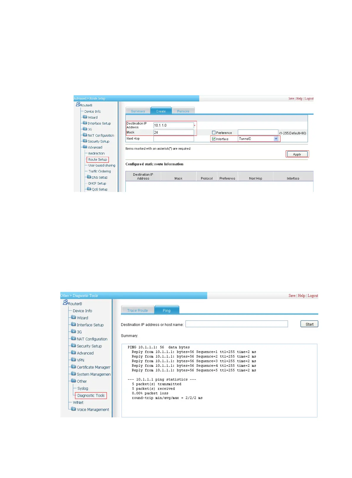
b. Click the Create tab and then perform the configurations shown in Figure 389.
c. Enter 10.1.1.0 as the destination IP address.
d. Enter the mask length 24.
e. Select the box before Interface, and then select egress interface Tunnel0.
f. Click Apply.
Figure 389 Adding a static route from Router B through interface Tunnel 0 to Group 1
Verifying the configuration
On Router B, ping the IP address of Ethernet 0/0 of Router A:
1. Select Other > Diagnostic Tools from the navigation tree of Router B.
2. Click the Ping tab.
3. Enter the destination IP address 10.1.1.1.
4. Click Start.
5. View the result of the ping operation in the Summary area.
Figure 390 Verifying the configuration
 Loading...