375
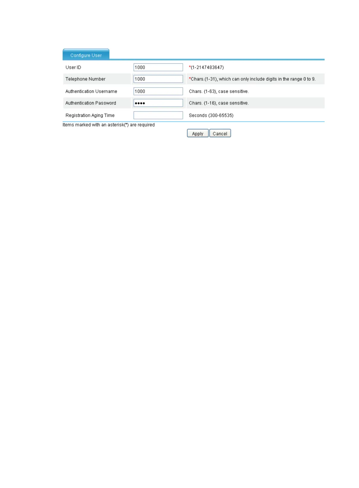
Figure 762 Configuring a user
7. Enter 1000 for User ID.
8. Enter 1000 for Telephone Number.
9. Enter 1000 for Authentication Username.
10. Enter 1000 for Authentication Password.
11. Click Apply.
# Configure user 5000 in the similar way.
Configuring Router A
1. Configure a local number in the local number configuration page: The ID is 1000, the number is
1000, the bound line is line2/0, the username is 1000, and the password is 1000.
2. Configure a call route to Router B in the call route configuration page: The ID is 5000, the
destination number is 5000, the routing type is SIP, and the SIP routing method is proxy server.
3. Configure SIP registration in the connection properties configuration page: Enable SIP
registration, and configure the main registrar’s IP address as 2.1.1.2.
Configuring Router B
1. Configure a local number in the local number configuration page: The ID is 5000, the number is
5000, the bound line is line2/0, the username is 5000, and the password is 5000.
2. Configure a call route to Router A in the call route configuration page: The ID is 1000, the
destination number is 1000, the routing type is SIP, and the SIP routing method is proxy server.
3. Configure SIP registration in the connection properties configuration page: Enable registration,
and configure the main registrar’s IP address as 2.1.1.2.
Verifying the configuration
• Select Voice Management > States and Statistics > Local Survival Service States from the
navigation tree. You can find that numbers 1000 and 5000 have been registered with the local
SIP server on Router C.
• Phones 1000 and 5000 can call each other through the local SIP server.
Configuring local SIP server to operate in alive mode
Network requirements
Router A and Router B carry out call services through the remote voice server VCX. Configure the
local SIP server on Router A to operate in alive mode, so that calls can be originated or received
through Router A when the VCX fails. When the VCX recovers, it will take over call services again.

 Loading...