FusionModule800 Smart Small Data Center
Installation Guide (Six Fans)
Copyright © Huawei Technologies Co., Ltd.
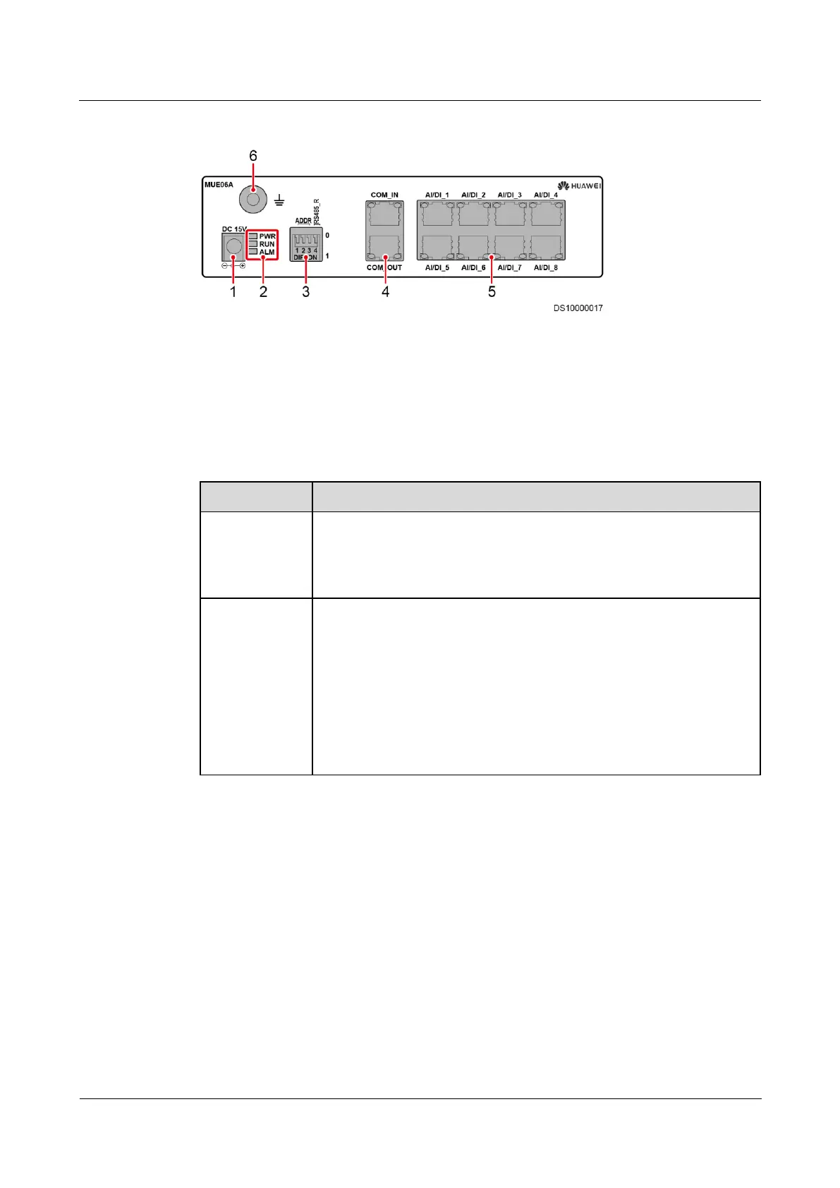
Figure 4-40 Ports on the front panel of the standalone AI/DI module
(1) DC 15 V power input port
Table 4-3 describes the ports on the front panel of the standalone AI/DI module.
Table 4-3 Description of ports on the front panel of the AI/DI module
Cascading ports. COM_IN connects to the RS485 port on the ECC800,
and COM_OUT connects to another standalone AI/DI module.
Pin definitions of the ports are the same as those of the COM4 port on
the communications card.
Provides 12 V DC outputs for sensors and are compatible with 4–20 mA
current signals, signals from current-based smoke sensors and water
sensors, dry contact signals, and NTC signals.
Pin definition:
3: 12 V DC, 54 mA
6: D-
7: D+
8: GND
Procedure
Step 1 Use a network cable to connect the COM_IN port on the independent deployment AI/DI
module to the COM3/12 V port on the ECC800.
----End
4.6.6 Connecting the Smoke Detector Monitoring Cable
Prerequisites
The smoke detector has been installed.
 Loading...