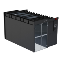
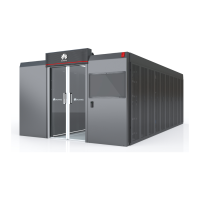
FusionModule800 Smart Small Data Center
Installation Guide (Six Fans)
Copyright © Huawei Technologies Co., Ltd.
Step 6 Connect the dehumidifier power cable.
1. Cut off the national standard three-pin plug of the power cable delivered with the
dehumidifier, and strip the power cable insulation layer for a proper length.
2. Strip the insulation layers of the brown and blue wires of cable 25030384 at both ends,
and wrap the yellow and green wires with insulation tape.
3. Crimp and connect the L and N wires of the dehumidifier power cable to the brown and
blue wires of cable 25030384 respectively using the cord end terminals delivered with
the dehumidifier.
4. Crimp the other end of the cable using cord end terminal 14170096 (brown wire) and OT
terminal 14170014 (blue wire), route the cable out of the cabinet top to the PDC through
the strong-current cable trough. Connect the brown wire to the 10 A circuit breaker or
lighting circuit breaker reserved in the PDC, and connect the blue wire to the N busbar in
the PDC.
5. Crimp the PE cable of the dehumidifier power cable using the OT terminal (M6)
delivered with the dehumidifier, and connect the crimped terminal to a nearby ground
point in the IT cabinet.
Step 7 Open the dehumidifier panel and start the dehumidifier, slowly pour water into the water
channel connected to the dehumidifier, and check that the water pump can drain water
smoothly.
Step 8 Reinstall the dehumidifier panel and, start the dehumidifier, and set the humidity for the
dehumidifier.
----End
A.6 Checking the Monitoring Parameters for the
Factory-Installed Devices
Table A-3 Parameter settings for factory-installed devices
COM1/12V port on
the ECC800
1. Set Equip Type_Enum to ATS.
2. Set COM to 1.
3. Set Device Address to 1.
The first smart
cooling product
The device is identified automatically and
no parameter setting is required.
The second smart
cooling product
The device is identified automatically and
no parameter setting is required.
COM2/12V port on
the ECC800
1. Set Equip Type_Enum to UPS.
2. Set COM to 2.
3. Set Device Address to 2. The actual
UPS address can be obtained from the
UPS liquid crystal display (LCD).
AI/DI_3 port on the
ECC800
1. Set AI/DI_3 Sensor to Enable.
2. Set AI/DI_3 Sensor Name to SPD.
3. AI/DI_3 Sensor Type is identified as
NC automatically.
 Loading...

