Maintenance Guide
12-6
12-2-2 Electrical Component Unit B
The electrical component unit B is mounted on the bottom left of the machine base frame.
Figures 12-2-2-1-1 to 12-2-2-1-2 show the external view. Figures 12-2-2-1-3 show the configuration
diagram.
Figures 12-2-2-1-4 to 12-2-2-1-6 show the EU connection diagram and POWER board circuit
diagram
The power supply unit B is composed of DC power supplies, control relays, and circuit protectors, and
designed to supply the DC power to the units (head unit including the Zθ-unit, X-Y unit, bank,
conveyor, etc.)
The following describes the application of each DC power supply. For the adjustment values, see the
QA Table, Adjustment of DC power output voltages.
・ +24V (PS1) General-purpose (For control unit outer board and motor driver, etc.)
・ +24VZ (PS2) For control of Z/ZA/T -servo amplifier
・ +24 V F BANK For front bank (feeder)
・ +24 V R BANK For rear bank (feeder)
・ +48V (PS3) For Z/θ-axis servo motor drive power
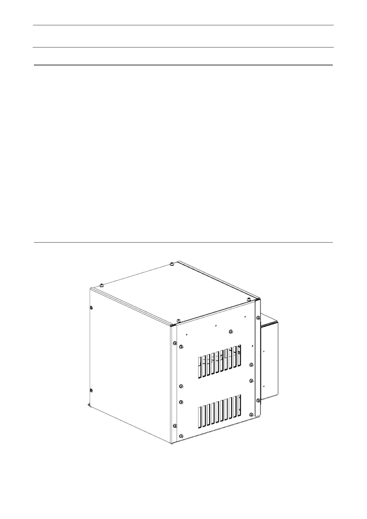
12-2-2-1 Configuration of Electrical Component Unit B
Figure 12-2-2-1-1 Outside View of Electrical Component Unit B
 Loading...