Maintenance Guide
12-26
12-3-5 SUPERIMPOSE BOARD (40129641)
[Functions]
This SUPERIMPOSE BOARD processes
the images to impose the images captured
by the camera on the Windows screen.
The board is controlled from the CPU
BOARD through the RS-232C.
The control function not only imposes the
images on the screen, but also changes
the image signals, captures the touch
panel control signals, and switches the CH
(front/rear monitor change-over).
[DIP switch settings]
There are no DIP switches on the
SUPERIMPOSE board.
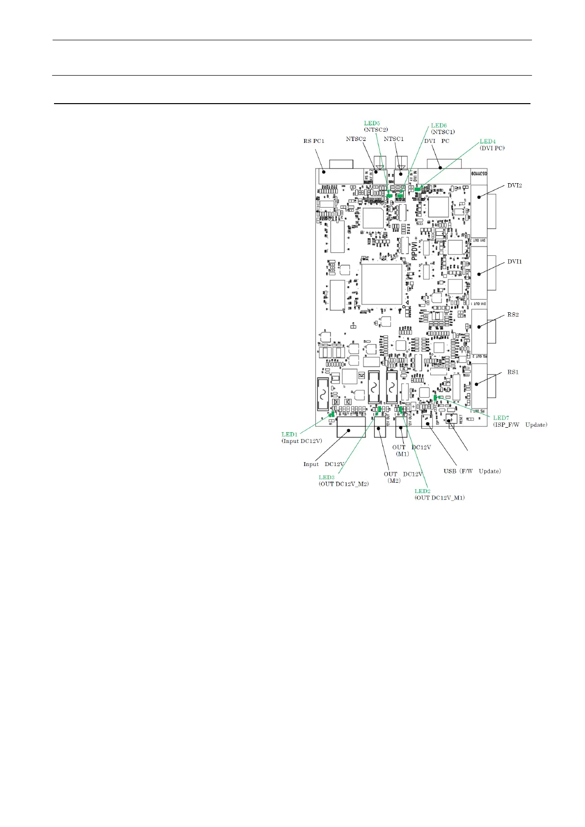
[Meaning of LED]
LED1 (lit in green):
Power ON (+12V)
LED2 (lit in green):
Power output (monitor 1)
LED3 (lit in green):
Power output (monitor 2)
LED4 : DVI signal input (lit in green.)
: No DVI signal (flashing in green.)
LED5 : NTSC1 signal input (lit in green.)
: No NTSC1 signal
(flashing in green.)
LED6 : NTSC2 signal input (lit in green.)
: No NTSC2 signal (flashing in green.)
LED7 : Hardware updating (flashing in green)
[Adjustment items after replacement]
There are no particular adjustment items.
[Replacement procedure]
① Before starting the replacement work, always turn OFF the main power, main circuit breaker,
and main switch.
② Since the SUPERIMPOSE BOARD is assembled into the PCB support located at the right
portion of the control box, take out the PCB support and replace it.
③ After the PCB support has been taken out, remove SL4030691SC (4 pcs.) to detach the
KEYBOARD/MOUSE selector (40003281).
④ Remove SL4030691SC (2 pcs.) and HX003540000 (4 pcs.) to detach the SUPERIMPOSE
board.
⑤ Replace the detached SUPERIMPOSE board with a new one and reassemble the parts and
components in the reverse order of disassembly.
 Loading...