Maintenance Guide
12-35
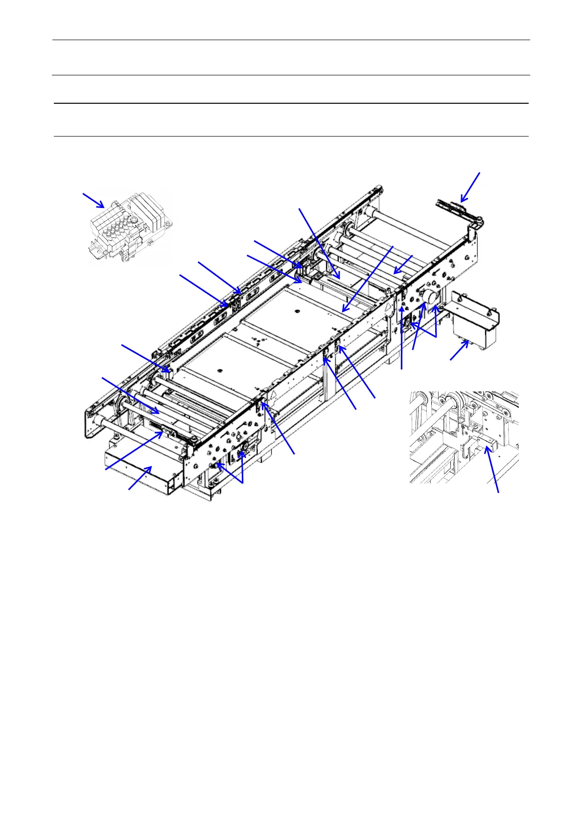
12-8 Transport Unit
12-8-1 Structure of Transport Unit
Figure 12-8-1-1 shows the structure drawing of the transport unit.
Figure 12-8-1-1
9 Support table origin sensor
10 Auto width adjustment origin
sensor
3 BU pin detection sensor light
emission
4 BU pin detection sensor light
reception
12 Transport motor driver
20 Transport solenoid valve
5 STOP sensor fiber light L
reception
13 Auto width adjustment motor
driver
→
R)
C-Out sensor (When R →L)
6 STOP sensor fiber light L
emission
→
L)
C-Out sensor (When L →R)
7 STOP sensor fiber light R
reception
15 Auto width adjustment encoder
8 STOP sensor fiber light R
emission
16 Auto width adjustment motor
 Loading...