Maintenance Guide
2-24
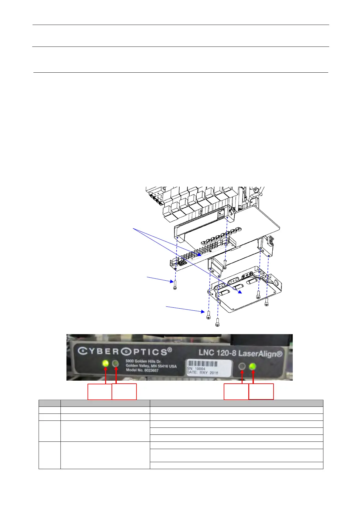
2-1-7 Replacing the LNC120-8
After the LNC120-8 has been replaced, it is absolutely necessary to re-input the MS parameters
related to the laser. (For details about input items, see section 2-2, Re-adjustment after Replacing the
Head.)
1) Remove cable fixing of LNC 120-8.
2) Remove the LNC120-8 on the underside.
3) Reassemble the components in the reverse order of disassembly.
4) After the power has been turned ON, make sure that LED5 and LED7 on the back of the
LNC120-8 are lit in green.
∗ Before mounting, eliminate Loctite sticking to the LNC support bracket as much as possible.
∗ After applying Loctite 243 to the LNC120-8 mounting screws, secure the screws ① with a
tightening torque of 1.0N・m and the screws ② with a tightening torque of 2.4N・m.
Ethernet connection status
• Lit in green while Ethernet is connected.
Ethernet communication status
• Blinks in yellow while Ethernet communicates correctly.
Sensor, host communication, and image
recognition preparation status
• Blinks in red immediately after the firmware has started up.
• Remains lit in red when invalid Ethernet is connected.
• Turns green when the sensor is ready to receive the command from the sensor.
Firmware initialization status
• Lit in red when the power is turned ON.
• Remains lit in red after the power has been turned ON when the firmware is not
loaded.
• Blinks in red and yellow alternately if it is failed to load the firmware.
①
Hexagon socket head
cap bolt M3 L=16
②
cap bolt M4 L=12
 Loading...