Maintenance Guide
5-20
5-8 Replacing the BU Pin Detection Sensor
1) Disconnect the sensor connectors from the board.
2) Cut the tie-up bands.
3) Remove the screws to detach the sensor.
4) Mount a new sensor.
5) Insert the sensor connectors to the board and secure the cables with the tie-up bands.
6) Adjust the light emission and light receiving sensor orientations to check that the sensor
receives the light correctly.
7) Adjust the sensitivity adjustment potentiometer on the light receiving side so that the sensor
status becomes as follows.
Table 5-8-1 Sensor Sensitivity Adjustment
Light emitting side
power ON
Light receiving side
stable detection
Light receiving
sensor ON
Sensor lighting color Orange Green Orange
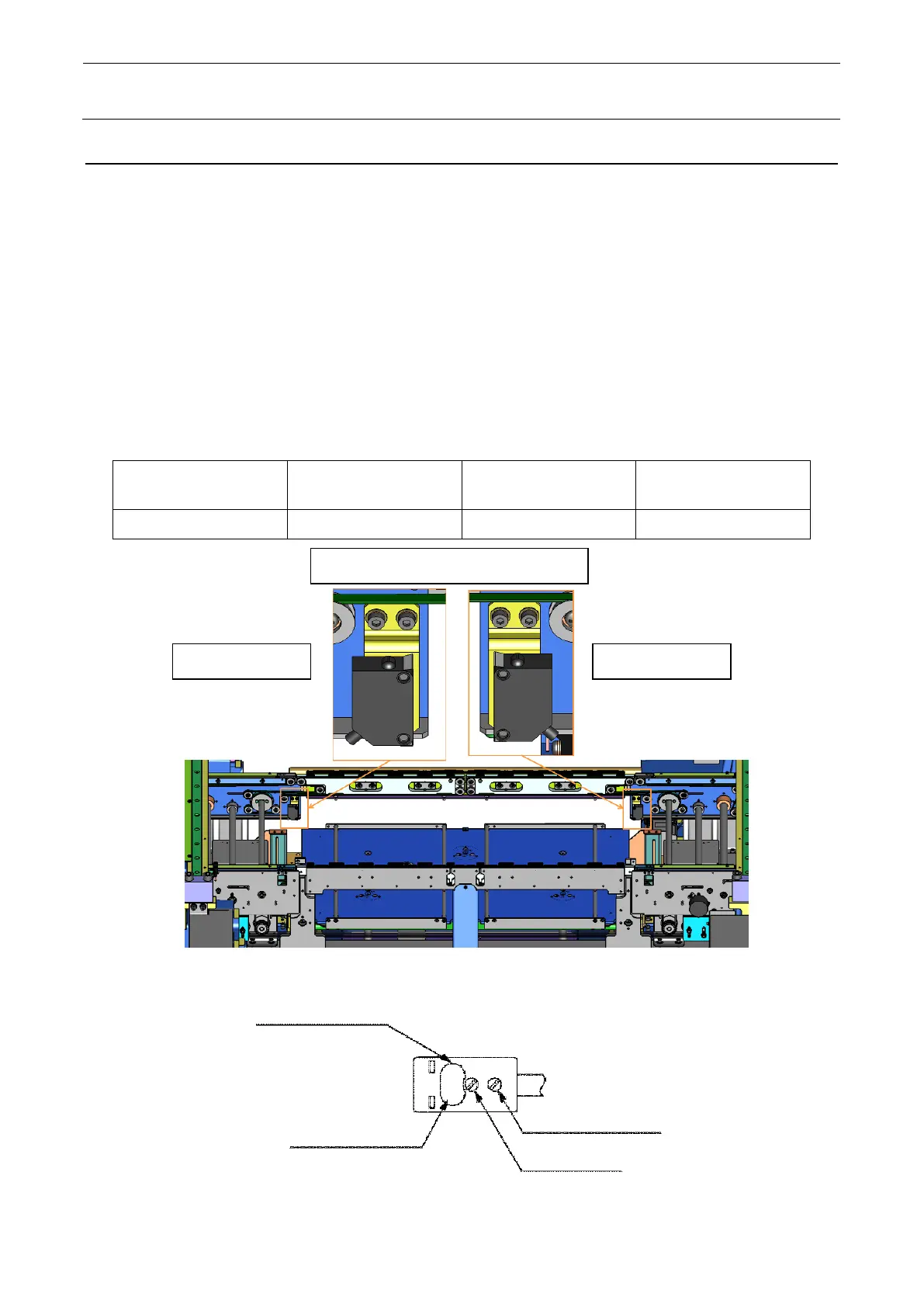
Figure 5-8-1 Sensor position
Figure 5-8-2 Details of Light Receiving Side
L assembly and attention to assembling R
indicator (orange)
(green)
change-over switch
potentiometer
Light emitting side Light receiving side
 Loading...