Maintenance Guide
12-48
12-11 E BANK RELAY PCB ASM (40128876)
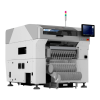
12-11-1 Outside View of Board
Figure 12-11-1-1 shows the outside view of E BANK RELAY PCB ASM.
Use this outside view as reference for the switch settings and volume adjustment described in the
following sections.
Figure 12-11-1-1 Outside View of E BANK RELAY PCB ASM
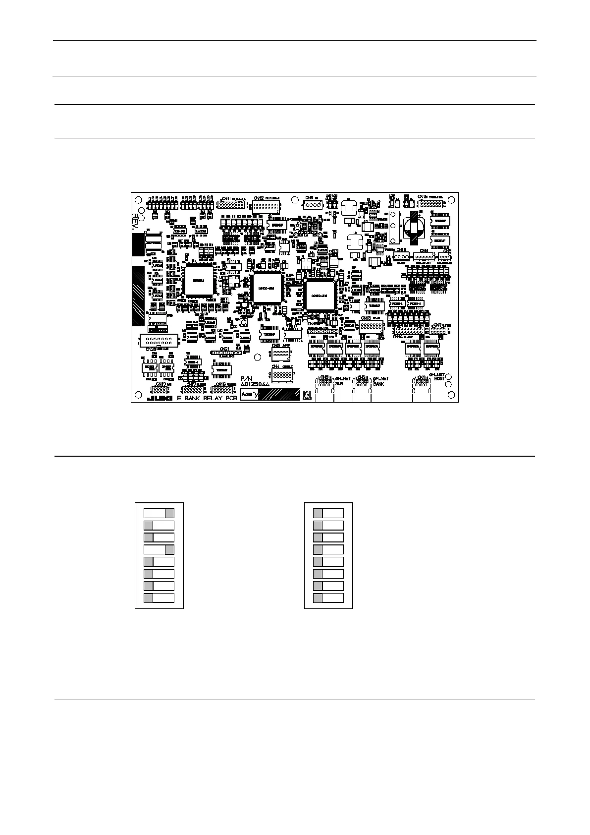
12-11-2 Setting the Switches
The switches have already been set at the delivery. Before mounting the PCB, check the switch
settings.
The SW 1 and 2 are intended for the function revision. For details, see the REV control table
(40129496).
12-11-3 Adjusting the Volumes
The volumes have already been adjusted at the delivery of the PCB. So, mount the PCB in the
machine and check the set voltage values. See “RS-1_QA Table E09_E BANK RELAY board VAC
sensor level adjustment”.
1
O
N
5
DSW3
1
O
N
5
DSW4
 Loading...