Do you have a question about the JUKI RS-1 and is the answer not in the manual?
| Brand | JUKI |
|---|---|
| Model | RS-1 |
| Category | Racks & Stands |
| Language | English |
Procedure for replacing the servomotor in the X-Y unit.
Steps for replacing limit and origin near sensors for X and Y axes.
Instructions for replacing the X and Y axis cableveyors.
Detailed steps for replacing cables within the X/Y veyor-cable assembly.
Procedure for disassembling and reassembling cableveyor links.
Comprehensive guide for replacing the X ball screw, including preparation.
Detailed steps for replacing the Y ball screw, including preparations.
Table outlining readjustment procedures after XY component replacement.
Procedures related to the 8-nozzle head unit.
Table specifying MS parameters to readjust after head unit replacement.
Steps for replacing the Z-motor with the head mounted on the machine.
Procedure for replacing the θ-motor with the head dismounted from the machine.
Instructions for replacing the Z-axis timing belts.
Procedure for replacing the θ-axis timing belt.
Steps for replacing the ball screw with the head dismounted from the machine.
Ball screw replacement procedure for specific head revision numbers.
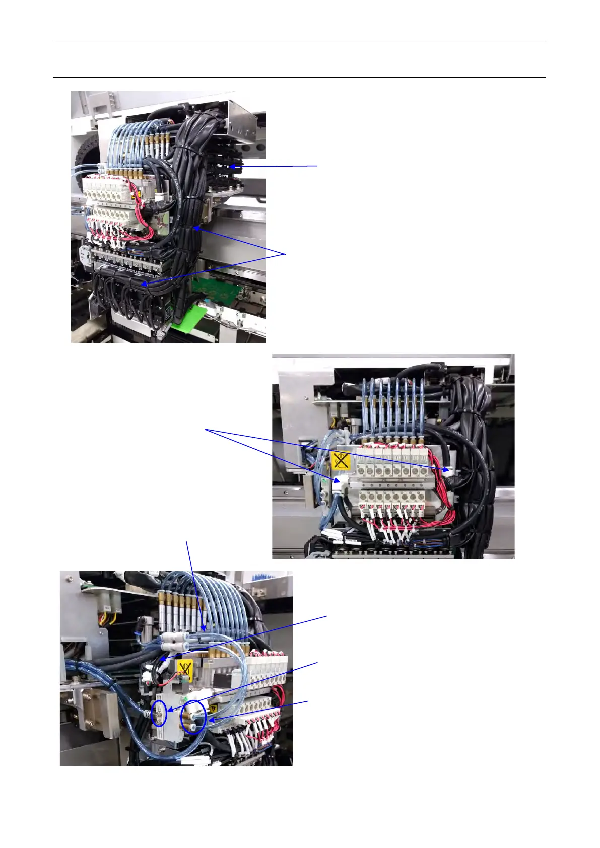
Procedures for replacing solenoid valves and related components.
Steps for replacing the head main board and servo amplifier board.
Procedure for replacing the OCC unit, including necessary adjustments.
Steps for replacing the CCD camera and lens assembly.
Procedure for replacing the OCC coaxial and angle light boards.
Steps for replacing the lens filter.
Guidance on adjusting focus and light quantity for the OCC unit.
Table listing readjustment items after OCC unit replacement.
Procedure for replacing the transport belt, including tension adjustment.
Information on replacing transport pulleys A and B.
Steps for replacing the conveyor motor and adjusting belt tension.
Procedure for replacing the AWC motor and adjusting belt tension.
Instructions for replacing timing belts related to transport width adjustment.
Steps for replacing left and right sensors and adjusting sensitivity.
Procedures for replacing front and rear stop sensor fibers.
Steps for replacing the BU pin detection sensor.
Procedure for replacing the support table origin sensor.
Steps for replacing the AWC origin sensor.
Procedures for replacing the support table motor, including component removal.
Steps for replacing the backup stopper and adjusting its position.
Procedure for replacing the support guide cylinder.
Instructions for switching conveyor direction via sensor and software settings.
Steps for replacing the mechanical stopper sensor and cylinder.
Procedure for replacing the CAL block board assembly.
Steps for replacing the ejector assembly.
Procedure for replacing the ATC air cylinder and adjusting its position.
Steps for replacing ATC open and close sensors.
Guidance on adjusting the speed controller for ATC slide plate.
Introduction to feeder bank types: fixed and exchange trolley.
Procedures for replacing mechanical valves, bank up cylinders, selectors, and connectors.
Diagram showing the main components of the tape cutter.
Detailed steps for replacing the movable and fixed cutter blades.
Layout diagrams of feeder float sensors for different machine revisions.
Procedures for replacing old type light receiving and emitting side sensors.
Steps for replacing new type sensors.
Procedure for detaching and replacing push-button switches.
Detailed steps for replacing the emergency stop switch.
Procedure for replacing the cover open switch main unit.
Steps for replacing the safety cover lock cylinder.
Procedure for replacing the assist hinge.
Diagrams showing the layout of various electrical components on the machine.
Details on Electrical Component Units A and B, including their configurations.
Information about the control unit and its board layout.
Structure and adjustment of the XY-driver unit.
Configuration and components of the Z and T units.
Structure, connections, motor adjustments, and sensor lists for the transport unit.
Functions, pin settings, and LED indications of the SAFETY PCB.
Functions and replacement procedures for HEAD MAIN PCB and HEAD RELAY PCB.
Details on E BANK RELAY PCB, including switch settings and volume adjustment.
Information on LIGHT CONTROL PCB and filter element replacement.
Guidance on replacing consumable parts for the vacuum pump.
Procedure for replacing the LCD monitor and setting up the touch panel.
Steps for replacing the system disk (SSD) and required components.
Procedures for replacing bar-code reader and checking its operation.
Steps for replacing the VCS cylinder and its related parts.
Procedure for replacing the VCS sensor and checking its operation.
Steps for replacing the VCS camera switching cylinder.
Exploded view and part list for the VCS light unit assembly.
Procedures for replacing and adjusting the VCS camera.
Steps for replacing the solder recognition light board and adjusting the light.
Procedure for adjusting the light quantity of the solder recognition light.
Procedure for replacing the load cell and its amplifier, including parameter acquisition.
Steps for replacing the coplanarity sensor and obtaining offsets.
Procedure for changing the IP address of the coplanarity CPU via network settings.
Procedure for changing the CONTACT SUB UNIT of the CVS.
Steps for changing the CVS board.
Procedure for replacing the RFID READER/WRITER and obtaining offsets.