JUNOS Internet Software Network Operations Guide: Hardware
434 ! Understanding the HCM
The HCM has the following components:
! 100-Mbps Fast Ethernet switch—Carries signals and monitoring data between
router components.
! Two LEDs—Indicate HCM status. The green LED is labeled PWR and the blue
LED labeled
MSTR. See “HCM LEDs” on page 435 for a description of the LED
states.
! Alarm LEDs—Display alarm conditions, if any exist.
! PIC offline buttons—Relay a request to the CFEB, which prepares a PIC for
removal from the router, or brings the PIC online when it is replaced.
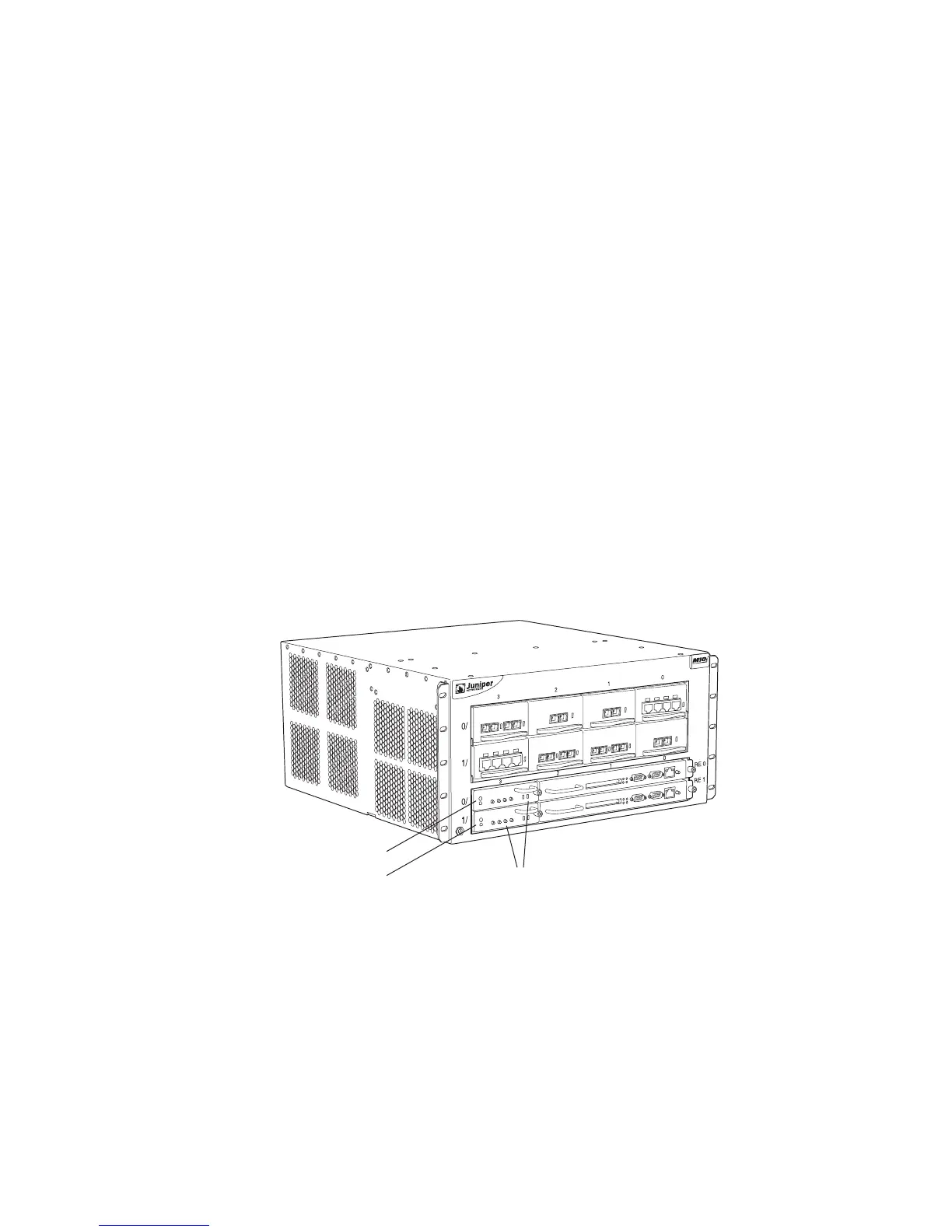
Two HCMs are installed into the midplane from the front of the chassis, as shown in
Figure 174. The master HCM performs all functions and provides PIC removal
buttons for the first FPC. The standby HCM provides PIC removal buttons for the
second FPC. The HCM in the slot labeled
HCM0 is paired with the Routing Engine in
the slot labeled
RE0. Likewise, the HCM in the slot labeled HCM1 is paired with the
Routing Engine in the slot labeled
RE1. By default, the HCM in the slot labeled
HCM0 is the master.
Figure 174: M10i Router HCM Location
The HCM is hot-pluggable.
g002162
HCMs
HCM0
HCM1
M10i front
 Loading...