For a schematic diagram of the digital I/O hardware, refer to the Series 3700A Specifications on the
Keithley Instruments support website (https://www.tek.com/support).
High-current pins (pins 10 to 14) can be used for binning applications or for external relays.
GPIB connector
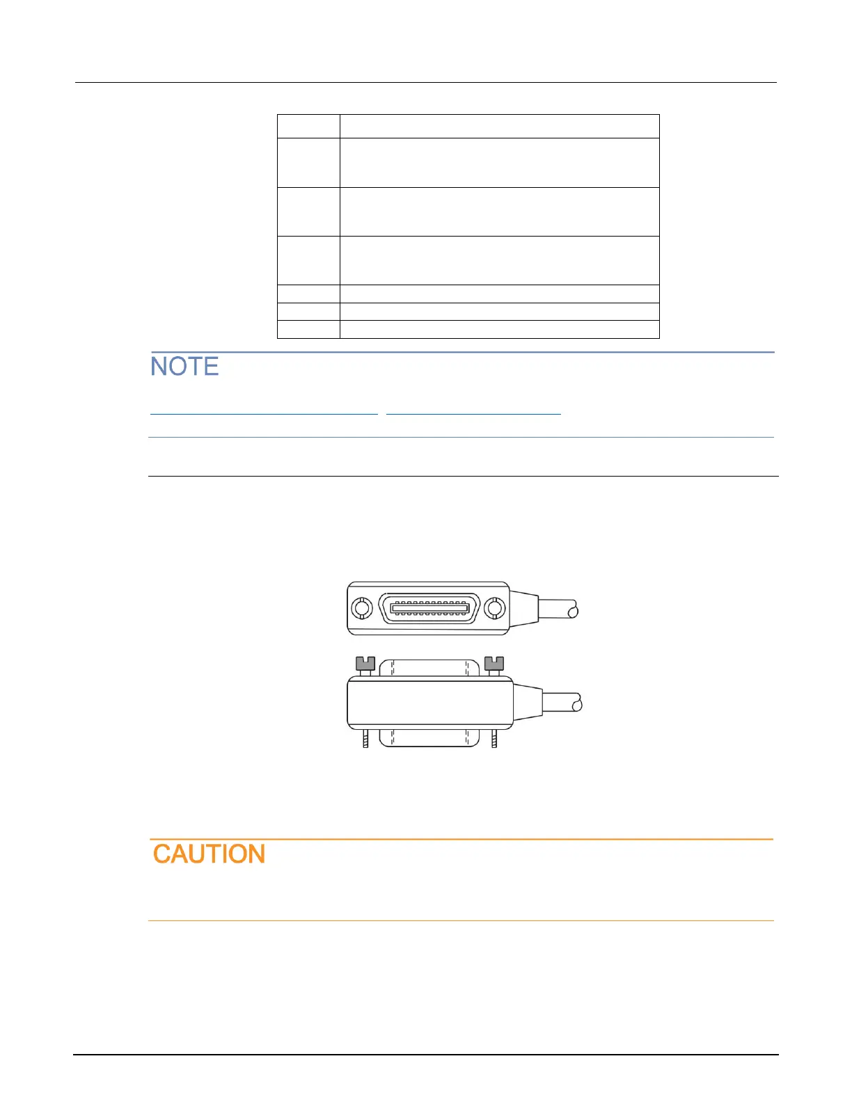
To connect a Series 3700A to the GPIB interface, use a cable equipped with standard GPIB
connectors, as shown below.
Figure 28: GPIB connector
To allow many parallel connections to one instrument, stack the connectors. Each connector has two
screws on it to ensure that connections remain secure. The figure below shows a typical connection
diagram for a test system with multiple instruments.
To avoid possible mechanical damage, stack no more than three connectors on any one
instrument. To minimize interference caused by electromagnetic radiation, use only shielded
GPIB cables. Contact Keithley Instruments for shielded cables.
 Loading...


