16 ENGINE 121
– Mount and tighten screw A with the washer.
Guideline
Locking screw for bearing M5 6 Nm
(4.4 lbf ft)
Loctite
®
243™
– Press in the shaft seal ring of countershaft 2 and shift shaft 3 with the open side
facing inwards so that it is flush.
– Mount and tighten the oil jet 1.
Guideline
Oil jet, piston cooling M6x0.75 4 Nm
(3 lbf ft)
Loctite
®
243™
– Mount the dowels.
– Blow compressed air through all oil channels and check that they are clear.
200155-10
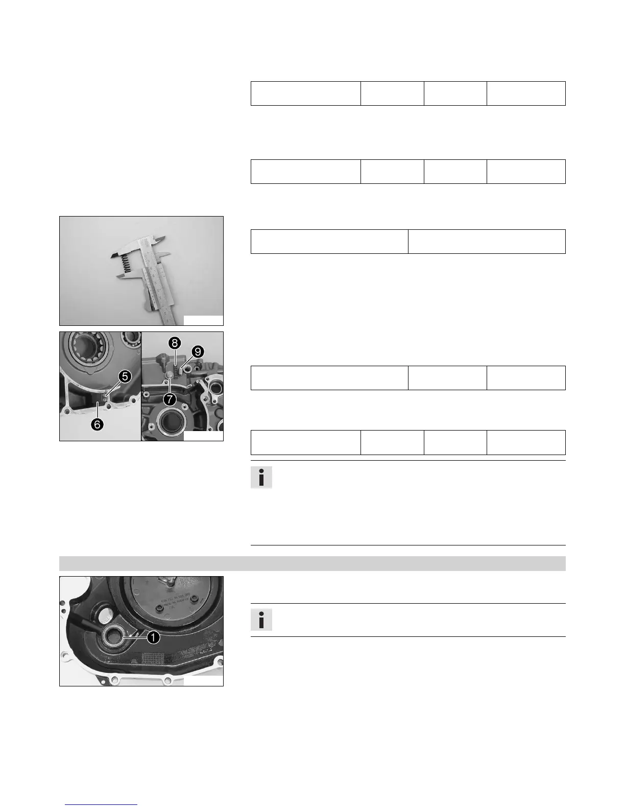
– Measure the spring length of the oil pressure regulator valve.
Oil pressure regulator valve - minimum
spring length
25.36 mm (0.9984 in)
» If the measured value does not equal the specified value:
– Change the spring.
– Check the piston valve for damage and wear.
» If there is damage or wear:
– Replace the piston valve.
300093-10
– Lubricate piston valve 9 and mount it with pressure spring 8. Mount and tighten
screw plug 7 with the new seal ring.
Guideline
Oil pressure regulator valve plug M12x1.5 20 Nm
(14.8 lbf ft)
– Position the membrane support plate 5 with membrane 6. Mount and tighten the
screws.
Guideline
Screw, membrane fixation M3 2 Nm
(1.5 lbf ft)
Loctite
®
243™
Info
The membrane support plate is curved and must point away from the mem-
brane.
An incorrectly installed membrane support plate results in loss of perfor-
mance and increased oil consumption or leaks.
Do not apply thread locker between the membrane and the membrane sup-
port plate since this would impair their function.
16.4.3 Work on the clutch cover
300097-10
– Remove the shaft seal ring 1 of the crankshaft.
– Press in a new shaft seal ring with the open side facing inward until it stops.
Info
Support the clutch cover sufficiently when pressing in.
– Blow compressed air through the oil channel and check that it is clear.

 Loading...