16 ENGINE 150
16.5.12 Installing timing chain and timing chain sprocket
300150-10
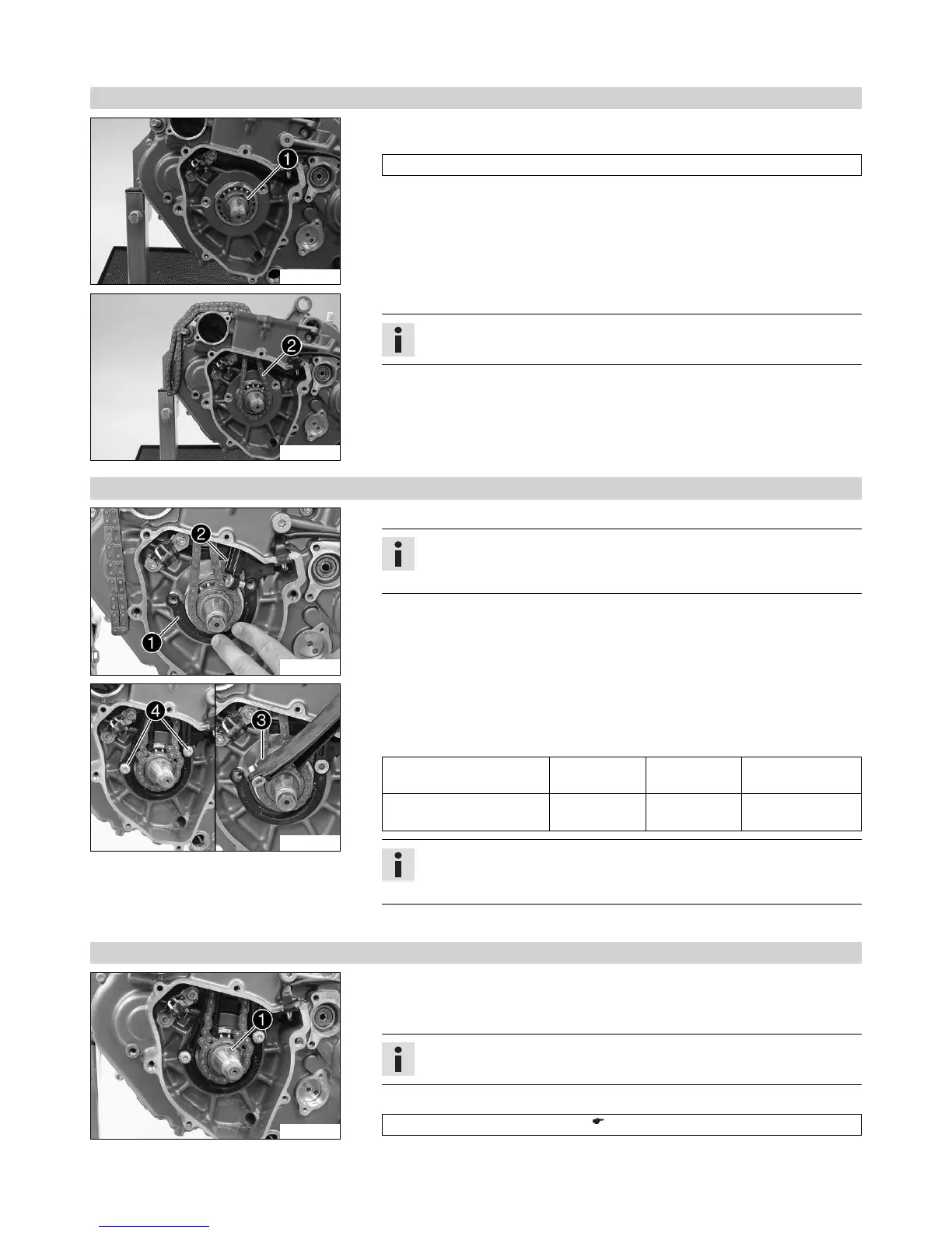
– Heat the timing chain sprocket and push it immediately on to the crankshaft.
Guideline
100 °C (212 °F)
– Mount lock ring 1.
300148-11
– Thread the timing chain 2 in and lay it over the timing chain sprocket.
Info
If the timing chain is not new, pay attention to the direction of travel.
16.5.13 Installing timing chain rails
300046-11
– Position the timing chain securing guide 1.
Info
The cable of the crankshaft position sensor must be laid in the cable chan-
nel of the timing chain securing guide.
– Thread in the timing chain tensioning rail 2 from above. Insert the support bush-
ing into the timing chain securing guide.
300045-11
– Thread in the timing chain guide rail 3 from above. Insert the support bushing into
the timing chain securing guide.
– Mount and tighten screws 4.
Guideline
Screw, timing chain guide
rail
M6 10 Nm
(7.4 lbf ft)
Loctite
®
243™
Screw, timing chain ten-
sioning rail
M6 10 Nm
(7.4 lbf ft)
Loctite
®
243™
Info
Ensure that there is no thread locking material at the collar of the screw;
otherwise, the timing chain tension rail could lock and break.
– Check both timing chain rails for freedom of motion.
16.5.14 Installing rotor
300042-10
– Ensure that the spring washer 1 is seated properly.
– Degrease the cone of the crankshaft and the rotor.
– Mount the rotor.
Info
Make sure that the crankshaft is not blocked.
– Use the special tool to hold the rotor tight.
Holding spanner (75029091000) ( p. 218)

 Loading...