16 ENGINE 124
– Install the crankshaft bearing inner ring. ( p. 124)
– Measure the axial clearance of the crankshaft and the balancer shaft. ( p. 125)
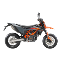
16.4.7 Checking crankshaft run-out at bearing pin
300132-10
– Position the crankshaft on a roller block.
– Rotate the crankshaft slowly.
– Check the crankshaft run-out at both bearing pins.
Crankshaft run-out at bearing pin ≤ 0.10 mm (≤ 0.0039 in)
» If the crankshaft run-out at the bearing pin is greater than the specified value:
– Align the crankshaft.
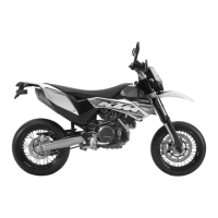
16.4.8 Installing balancer shaft drive wheel
302148-10
Main work
– Fix the crankshaft with special tools 1 and 2 in the vise.
Upper part, pressing-out tool (75029047050) ( p. 216)
Under part, pressing-out tool (75029047051) ( p. 216)
– Warm the drive wheel.
Guideline
100 °C (212 °F)
300159-10
– Place the drive wheel on the crankshaft.
The dowel of the crankshaft must fit in the drill hole 4.
The side of the drive wheel with the punch mark 3 must be visible after
assembly, and the side with the bevel 2 must be in contact with the
crankweb.
Finishing work
– Install the crankshaft bearing inner ring. ( p. 124)
– Measure the axial clearance of the crankshaft and the balancer shaft. ( p. 125)
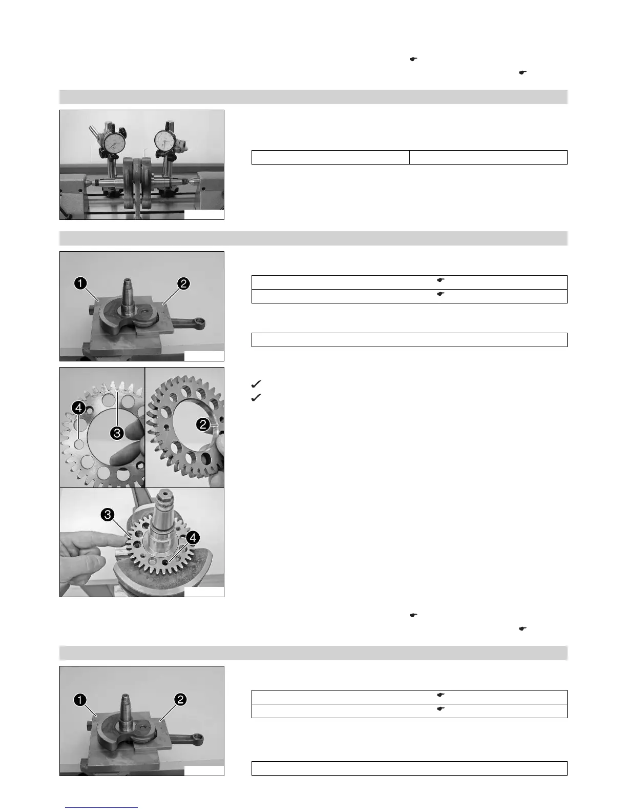
16.4.9 Installing crankshaft bearing inner ring
302150-10
Main work
– Fix the crankshaft with special tools 1 and 2 in the vise.
Upper part, pressing-out tool (75029047050) ( p. 216)
Under part, pressing-out tool (75029047051) ( p. 216)
– Push on the compensation shim.
– Heat the special tool. Install the inner bearing race.
Guideline
120 °C (248 °F)

 Loading...