ENGINE
B2301, B2601, WSM
1-S47
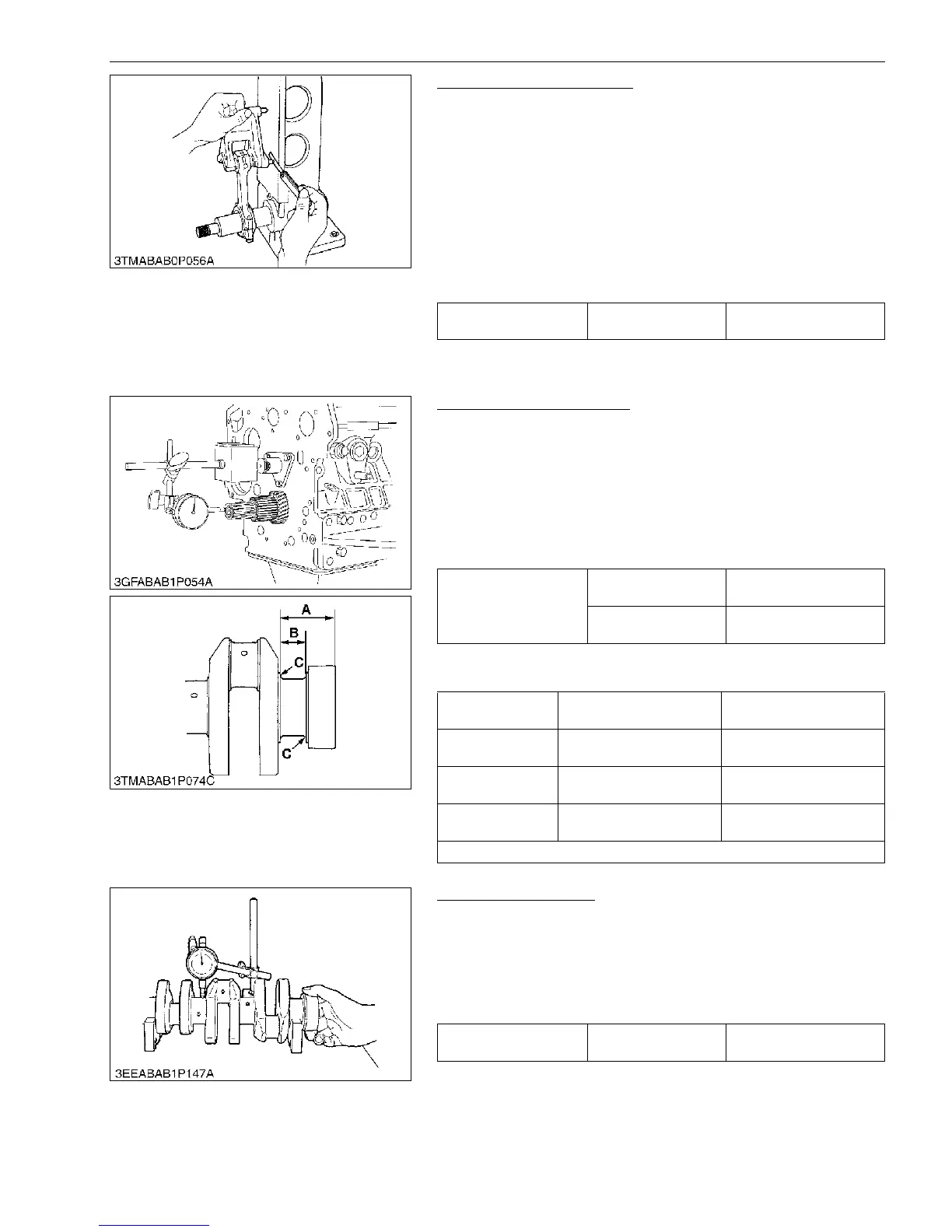
Connecting Rod Alignment
1. Remove the crankpin bearing, and install the connecting rod
cap.
2. Install the piston pin in the connecting rod.
3. Install the connecting rod on the connecting rod alignment tool.
4. Put a gauge over the piston pin, and move it against the face
plate.
5. If the gauge does not fit squarely against the face plate,
measure the space between the pin of the gauge and the face
plate.
6. If the measurement exceeds the allowable limit, replace the
connecting rod.
9Y1211156ENS0080US0
(4) Crankshaft
Crankshaft Side Clearance
1. Set a dial indicator with its tip on the end of the crankshaft.
2. Measure the side clearance by moving the crankshaft to the
front and rear.
3. If the measurement exceeds the allowable limit, replace the
thrust bearings.
4. If the same size bearing is useless because of the crankshaft
journal wear, replace it with an oversize one referring to the
table and figure.
(Reference)
• Oversize dimensions of crankshaft journal
9Y1211156ENS0081US0
Crankshaft Alignment
1. Support the crankshaft with V blocks on the surface plate at
both end journals.
2. Set a dial indicator with its tip on the intermediate journal.
3. Measure the crankshaft alignment.
4. If the measurement exceeds the allowable limit, replace the
crankshaft.
9Y1211156ENS0082US0
Space between gauge
pin face plate
Allowable limit
0.05 mm
0.002 in.
Crankshaft side
clearance
Factory specification
0.15 to 0.31 mm
0.0059 to 0.012 in.
Allowable limit
0.50 mm
0.020 in.
Oversize
0.20 mm
0.0079 in.
0.40 mm
0.016 in.
Dimension A
51.50 to 51.70 mm
2.028 to 2.035 in.
51.60 to 51.80 mm
2.032 to 2.039 in.
Dimension B
28.20 to 28.25 mm
1.111 to 1.112 in.
28.40 to 28.45 mm
1.119 to 1.120 in.
Dimension C
2.3 to 2.7 mm radius
0.091 to 0.10 in. radius
2.3 to 3.7 mm radius
0.091 to 0.10 in. radius
The crankshaft journal must be fine-finished to higher than Rmax = 0.8S.
Crankshaft alignment Allowable limit
0.02 mm
0.0008 in.

 Loading...