ELECTRICAL SYSTEM
B2301, B2601, WSM
8-M5
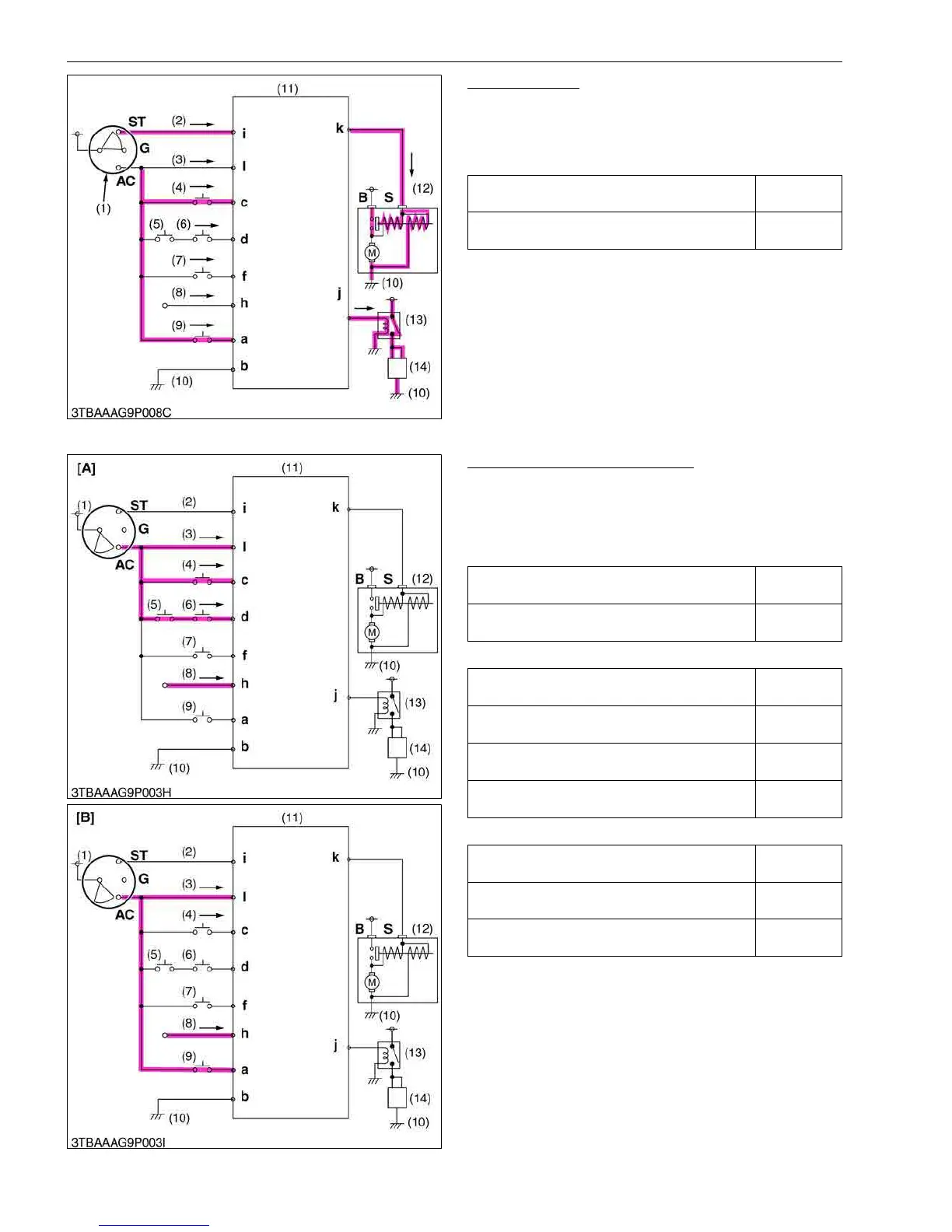
Engine Starting
When the following conditions become complete,
output voltage (12 V) reaches coil terminal of the starter
motor from controller k terminal, the engine can be
started.
9Y1211156ELM0006US0
One Second Delay Engine Stop
When one condition of the three patterns becomes
complete, output voltage (12 V) to the relay (engine stop
solenoid) from controller j terminal will stop in one
second delay.
Pattern 1
Pattern 2
Pattern 3
9Y1211156ELM0007US0
PTO Clutch Lever Switch
(Disengaged: ON, Engaged: OFF)
ON
HST Pedal Switch
(Neutral: ON, Forward and Reverse: OFF)
ON
(1) Key Switch
(2) ST Terminal Lead
(3) AC Terminal Lead
(4) PTO Clutch Lever Switch
(5) PTO Select Lever Switch
(6) Seat Tilt Switch
(7) Seat Switch
(8) Regulator
(9) HST Pedal Switch
(10) Frame Earth
(11) Controller
(12) Starter Motor
(13) Relay (Engine Stop
Solenoid)
(14) Engine Stop Solenoid
ST, G, AC: Key Switch
Terminals
a to l: Controller Terminals
B: Starter Motor B Terminals
S: Starter Motor S Terminal
→: Current Flow
Seat Switch
(Occupied: ON, Vacant: OFF)
OFF
HST Pedal Switch
(Neutral: ON, Forward and Reverse: OFF)
OFF
Seat Switch
(Occupied: ON, Vacant: OFF)
OFF
PTO Clutch Lever Switch
(Disengaged: ON, Engaged: OFF)
OFF
Seat Tilt Switch
(Tilted : ON, Normal : OFF)
OFF
PTO Select Lever Switch
(Rear PTO: ON, Rear/Mid or Mid PTO: OFF)
ON
Seat Switch
(Occupied: ON, Vacant: OFF)
OFF
PTO Clutch Lever Switch
(Disengaged: ON, Engaged: OFF)
OFF
PTO Select Lever Switch
(Rear PTO: ON, Rear/Mid or Mid PTO: OFF)
OFF
(1) Key Switch
(2) ST Terminal Lead
(3) AC Terminal Lead
(4) PTO Clutch Lever Switch
(5) PTO Select Lever Switch
(6) Seat Tilt Switch
(7) Seat Switch
(8) Regulator
(9) HST Pedal Switch
(10) Frame Earth
(11) Controller
(12) Starter Motor
(13) Relay (Engine Stop
Solenoid)
(14) Engine Stop Solenoid
[A] Pattern 2 and 3
[B] Pattern 1
ST, G, AC: Key Switch
Terminals
B: Starter Motor B Terminal
S: Starter Motor S Terminal
a to l: Controller Terminals
→: Current Flow

 Loading...