EasyManuals Logo

Kubota B2301 Workshop Manual

Kubota B2301
341 pages
To Next Page IconTo Next Page
To Previous Page IconTo Previous Page
Page #264 background imageLoading...
Page #264 background image
HYDRAULIC SYSTEM
B2301, B2601, WSM
7-M5
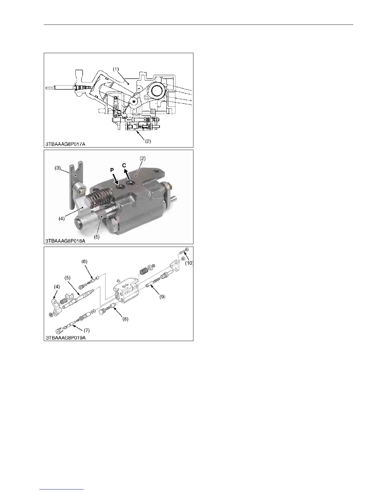
[3] POSITION CONTROL VALVE
(1) Structure
This position control valve (2) is located under the
hydraulic cylinder block (1).
This control valve is mechanically connected to the
position control lever with linkage.
This control valve is also mechanically connected to
the lift arm with a feed back rod.
This control valve controls the oil flow forced from
hydraulic pump and the oil returned back from the
hydraulic cylinder.
9Y1211156HYM0005US0
(1) Hydraulic Cylinder Block
(2) Position Control Valve
(3) Link
(4) Lever
(5) Spool
(6) Poppet
(7) Poppet
(8) Poppet
(9) Poppet
(10) Set Screw
P: Pump Port
C: Cylinder Port
KiSC issued 11, 2014 A

Table of Contents

Other manuals for Kubota B2301

Questions and Answers:

Question and Answer IconNeed help?

Do you have a question about the Kubota B2301 and is the answer not in the manual?

Kubota B2301 Specifications

General IconGeneral
Engine TypeDiesel
Transmission TypeHydrostatic
TypeCompact Utility Tractor
Drive4WD
3-Point Hitch CategoryCategory I
Fuel Capacity6.1 gallons
Hydraulic System Capacity3.7 gallons

Related product manuals