ELECTRICAL SYSTEM
B2301, B2601, WSM
8-S20
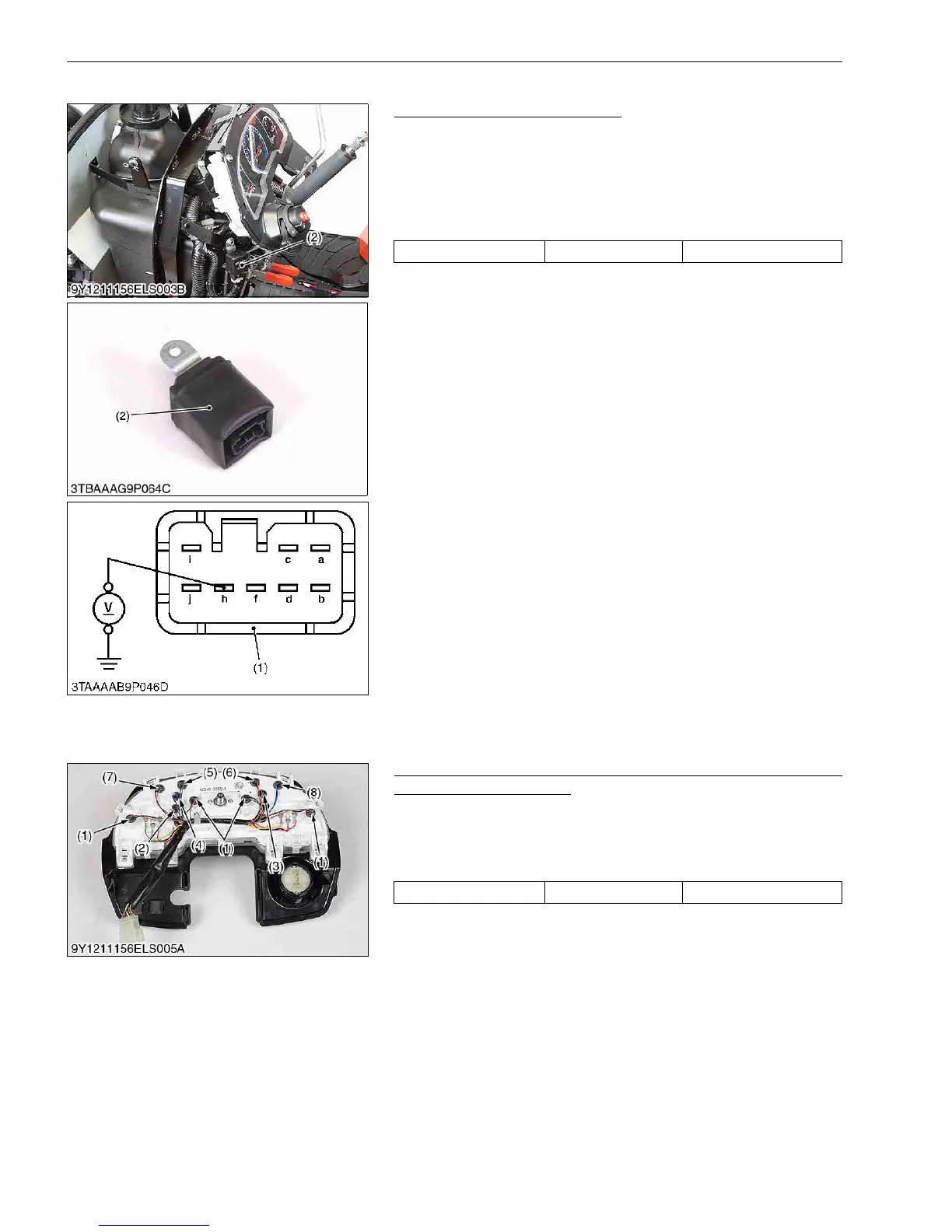
(2) Flasher Unit
Flasher Unit Connector Voltage
1. Remove the instrument panel.
2. Disconnect the connector (1) from the flasher unit (2).
3. Measure the voltage with a voltmeter across the h terminal and
chassis.
4. If the voltage differ from the battery voltage, the wiring harness
is damaged.
9Y1211156ELS0036US0
[7] WARNING LAMP, INDICATOR LAMP AND GAUGE
(1) Instrument Panel
Monitor Lamp (for Charge, Engine Oil Pressure, Pre-heat,
Illumination and Hazard)
1. Removing the meter panel from the tractor.
2. Remove the each lamp.
3. Measure the lamp resistance.
4. If it is infinity, replace the lamp with new.
9Y1211156ELS0037US0
Voltage h terminal – Chassis Approx. battery voltage
(1) Connector
(2) Flasher Unit
a: Frame Earth
b: Hazard Input
c: Vacant
d: Turn Signal (Left) Input
f: Turn Signal (Right) Output
h: Battery
i: Turn Signal (Left) Output
j: Turn Signal (Right) Input
All lamp Lamp specification 12 V, 1.7 W
(1) Illumination
(2) Pre-heat
(3) Hazard
(4) Charge
(5) Engine Oil Pressure
(6) Position
(7) Turn (R)
(8) Turn (L)

 Loading...