ELECTRICAL SYSTEM
B2301, B2601, WSM
8-S15
(3) OPC Controller
OPC Controller
1. Check the "Engine Starting Conditions" and "Automatic Engine
Stop Conditions". (See page 8-M5.)
2. If the tractor does not operate appropriately, check all parts
according to the "1.TROUBLESHOOTING" section.
3. If all parts except the OPC controller (1) is not damaged, replace
the OPC controller (1).
9Y1211156ELS0018US0
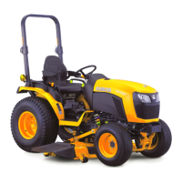
(4) Engine Stop Solenoid
Connector Voltage
1. Disconnect the 2P connector from engine stop solenoid.
2. Turn the key switch key to the "ON" position.
3. Measure the voltage with voltmeter between the terminal 1,
terminal 2 of wiring harness side and body.
4. If the voltage differs from the battery voltage, the wiring harness
or key switch is damaged.
9Y1211156ELS0019US0
Engine Stop Solenoid Test
1. Disconnect the lead from the engine stop solenoid after turning
the key switch off.
2. Connect jumper leads from the battery positive terminal to the
engine stop solenoid terminal 1 and 2, then from the battery
negative terminal to the engine stop solenoid body.
3. If the solenoid plunger is not attracted, the engine stop solenoid
is damaged.
9Y1211156ELS0020US0
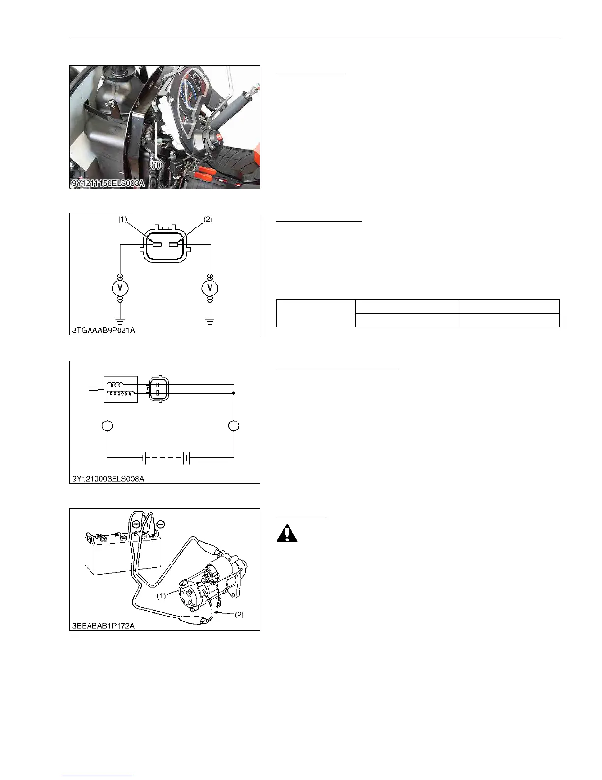
(5) Starter
Motor Test
• Secure the starter to prevent it from jumping up and down
while testing the motor.
1. Disconnect the battery negative cable from the battery.
2. Disconnect the battery positive cable and the leads from the
starter B terminal.
3. Remove the starter from the engine.
4. Disconnect the connecting lead (2) from the starter C terminal
(1).
5. Connect a jumper lead from the connecting lead (2) to the
battery positive terminal post.
6. Connect a jumper lead momentarily between the starter motor
housing and the battery negative terminal post.
7. If the motor does not operate, check the motor.
9Y1211156ELS0021US0
(1) OPC Controller
Voltage
Terminal 1 – Body Approx. battery voltage
Terminal 2 – Body Approx. battery voltage
(1) Terminal 2 (2) Terminal 1
(1) Battery
(1) C Terminal (2) Connecting Lead

 Loading...