HYDRAULIC SYSTEM
B2301, B2601, WSM
7-M9
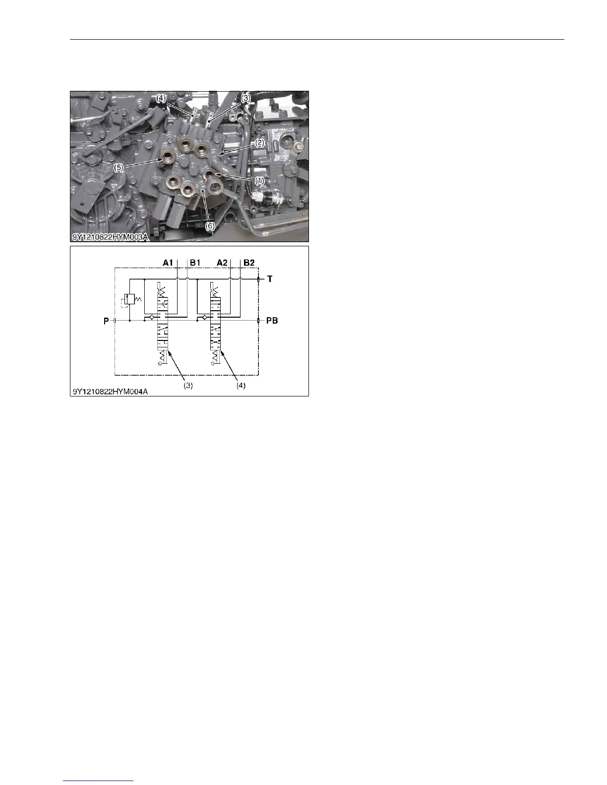
4. FRONT LOADER CONTROL VALVE
[1] STRUCTURE
The control valve assembly consists of one casting
block and four major section as shown above.
1) Inlet and Outlet Section
This section has P and T ports.
The P port is connected to the OUTLET port of
hydraulic block by the hydraulic hose.
The T port is connected to the TANK port of
hydraulic block by the hydraulic hose.
2) Boom Control Section
The boom control valve is consists of 4-position,
6-connection, detent, spring center type, consisting of a
mono block valve housing, spool, load check valve, etc.
This valve has A1 and B1 ports and controls oil flow to
the boom cylinder.
3) Bucket Control Section
The bucket control valve is consists of 4-position,
6-connection, no detent, spring center type, consisting of
a mono block valve housing, spool, load check valve,
etc. This valve has A2 and B2 ports and controls oil flow
to the bucket cylinder.
4) Power Beyond
This section has PB port which is connected to the
INLET port of hydraulic block by the hydraulic hose, and
feeds oil to the 3-point hitch hydraulic control valve.
9Y1211156HYM0011US0
(1) Pump Port
(2) Tank Port
(3) Boom Control Spool
(4) Bucket Control Spool
(5) Power Beyond Port
(6) Loader Valve Assembly
P: P Port
T: T Port
A1: A1 Port
A2: A2 Port
B1: B1 Port
B2: B2 Port
PB: PB Port

 Loading...