STEERING
B2301, B2601, WSM
6-M2
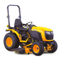
2. STEERING CONTROLLER
The steering controller consists of a control valve (4)
and a metering device (3).
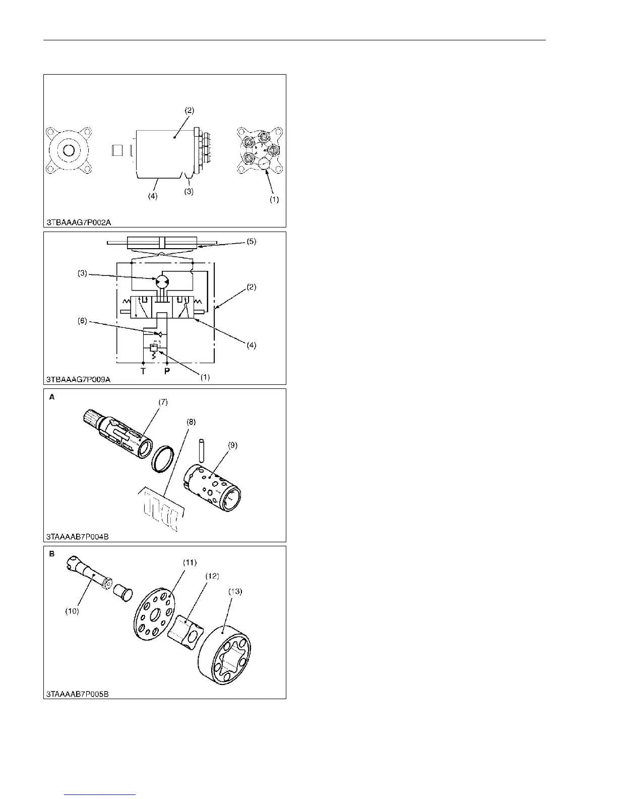
Control Valve
The control valve is a rotating spool type. When the
steering wheel is not turned, the position of the spool (7)
and sleeve (9) is kept neutral by the centering spring (8).
This causes the forming of a "Neutral" oil circuit. When
the steering wheel is turned either clockwise or
counterclockwise, the position of the spool and sleeve
changes in relation to the centering spring. This allows
the forming of a "Right Turning" or "Left Turning" oil
circuit. At the same time, the gear pump (Metering
device) rotates with the spool and sends the oil to the
cylinder corresponding to the rotation of the steering
wheel.
Metering Device
An oil, sent from the hydraulic pump to the steering
cylinder, passes through the metering device (3).
Namely, when the rotor is driven, two chambers suck in
oil due to volumetric change in the pump chambers
formed between the rotor (12) and the stator (13), while
oil is discharged from other two chambers. On the other
hand, rotation of the steering wheel is directly
transmitted to the rotor through the spool (7), drive shaft
(10), etc. Accordingly, the metering device serves to
supply the steering cylinder with oil, amount of which
corresponds to the rotation of the steering wheel. The
wheels are thus turned by the angle corresponding to the
rotation of the steering wheel. When the engine stops or
the hydraulic pump malfunctions, the metering device
functions as a manual trochoid pump, which makes
manual steering possible.
Relief Valve
The relief valve (1) is located in the steering
controller. It controls the maximum pressure of the
power steering system.
Its setting pressure is as follows
11.5 to 12.5 MPa
118 to 127 kgf/cm
2
1670 to 1810 psi
9Y1211156STM0002US0
(1) Relief Valve
(2) Steering Controller
(3) Metering Device
(4) Control Valve
(5) Steering Cylinder
(6) Check Valve
(7) Spool
(8) Centering Spring
(9) Sleeve
(10) Drive Shaft
(11) Distributor Plate
(12) Rotor
(13) Stator
A: Control Valve
B: Metering Device
P: P Port (from Hydraulic
Pump)
T: T Port (to Independent PTO
Clutch Valve and HST
Circuit)

 Loading...