ELECTRICAL SYSTEM
B2301, B2601, WSM
8-S12
[3] RELAYS
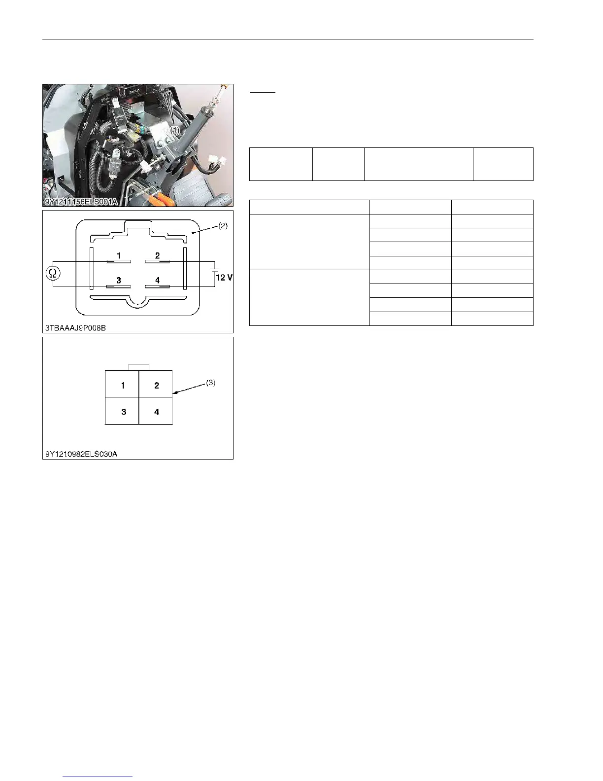
(1) Relays
Relay
1. Remove the relay.
2. Apply battery voltage across 2 terminal and 4 terminal, and
check for continuity across 1 terminal and 3 terminal.
3. If 0 Ω is not indicated, renew the relay.
Color of wiring (To identify the each relay position)
9Y1211156ELS0011US0
Resistance
1 terminal –
3 terminal
Battery voltage is applied
across 2 terminal and 4
terminal
0 Ω
Item Terminal No. Color of Wiring
Relay (Engine Stop Solenoid)
1R
2WL
3RL
4B
Relay (R2)
1R
2RB
3YL
4B
(1) Relay
(2) Connector (Relay)
(3) Connector (Wire Harness)

 Loading...