HYDRAULIC SYSTEM
B2301, B2601, WSM
7-M6
(2) Operation
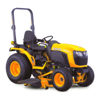
Neutral
Oil forced into the control valve through P port
pushes and opens the unload valve (3), and opens the
unload valve (3), and then returns to the transmission
case through T1 port.
Oil behind the unload valve (3) returns to the
transmission case through the groove of the spool (2).
Since the check valve (9) and the poppet 2 (5) are
closed, oil in the hydraulic cylinder does not flow to the
transmission case. Thus, the implement remains at its
fixed position.
9Y1211156HYM0006US0
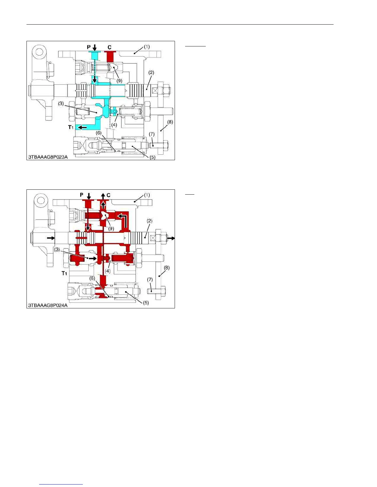
Lift
When the position control lever is set to "LIFT"
position, the spool (2) is pushed into the valve body (1).
The oil forced into the control valve body (1) through
P port flows to two oil circuits.
The first circuit is oil flowing to the back of the unload
valve (3) to close it.
The second oil circuit is oil flowing to the check valve
(9) and the hydraulic cylinder through C port to lift the
implement.
9Y1211156HYM0007US0
(1) Valve Body
(2) Spool
(3) Unload Valve
(4) Unload Poppet
(5) Poppet 2
(6) Sleeve
(7) Adjusting Bolt
(8) Connecting Plate
(9) Check Valve
P: Pump Port
C: Cylinder Port
T1: Tank Port
(1) Valve Body
(2) Spool
(3) Unload Valve
(4) Unload Poppet
(5) Poppet 2
(6) Sleeve
(7) Adjusting Bolt
(8) Connecting Plate
(9) Check Valve
P: Pump Port
C: Cylinder Port
T1: Tank Port
 Loading...