TRANSMISSION
B2301, B2601, WSM
2-M26
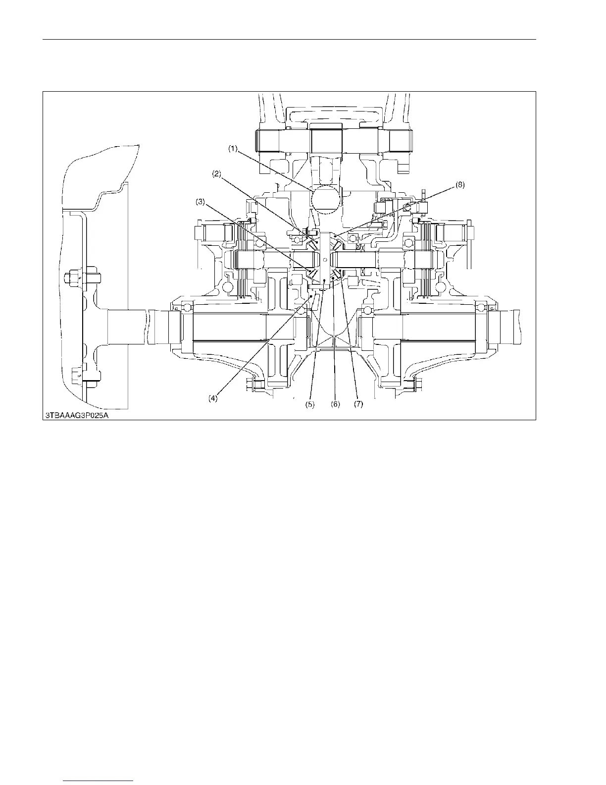
8. DIFFERENTIAL GEAR SYSTEM
[1] DIFFERENTIAL FUNCTION
During Straight Running
Rotation of the spiral bevel pinion (1) is transmitted to the spiral bevel gear (4) and differential case (8). When
road resistance to the right and left wheels are equal, differential pinions (2), (6) and differential side gears (3), (7) are
all rotate as a unit. Both rear axles received equal input, and both wheels turn at the same speed, allowing the tractor
to straight ahead. At this time, differential pinions (2), (6) does not rotate around the differential pinion shaft (5).
During Turning
When the tractor turns, the road resistance to the inside tire increases (as if braking is applied to that side only).
In other words, if one of tires slows down, revolution difference is generated in the differential side gears (3), (7).
When rotation of one differential side gear becomes lower than the other, differential pinions (2), (6) begin rotating
around differential pinion shaft (5). The other differential side gear is increased in speed by the speed increment of
differential pinion shaft (5). This means that rotation of one rear axle is slowed down and that of the other rear axle is
increased. Thus, the tractor turns smoothly without power loss.
The combined number of revolutions of the right and left differential side gears is always twice that of the spiral
bevel gear (4). When spiral bevel gear revolution is 100 min
-1
(rpm), and if one of the differential side gears stops
moving, the revolution of the other differential side gear becomes 200 min
-1
(rpm) and if one rotates at 50 min
-1
(rpm),
the other rotates at 150 min
-1
(rpm).
9Y1211156TRM0024US0
(1) Spiral Bevel Pinion
(2) Differential Pinion
(3) Differential Side Gear
(4) Spiral Bevel Gear
(5) Differential Pinion Shaft
(6) Differential Pinion
(7) Differential Side Gear
(8) Differential Case
 Loading...