ELECTRICAL SYSTEM
B2301, B2601, WSM
8-S13
[4] STARTING SYSTEM
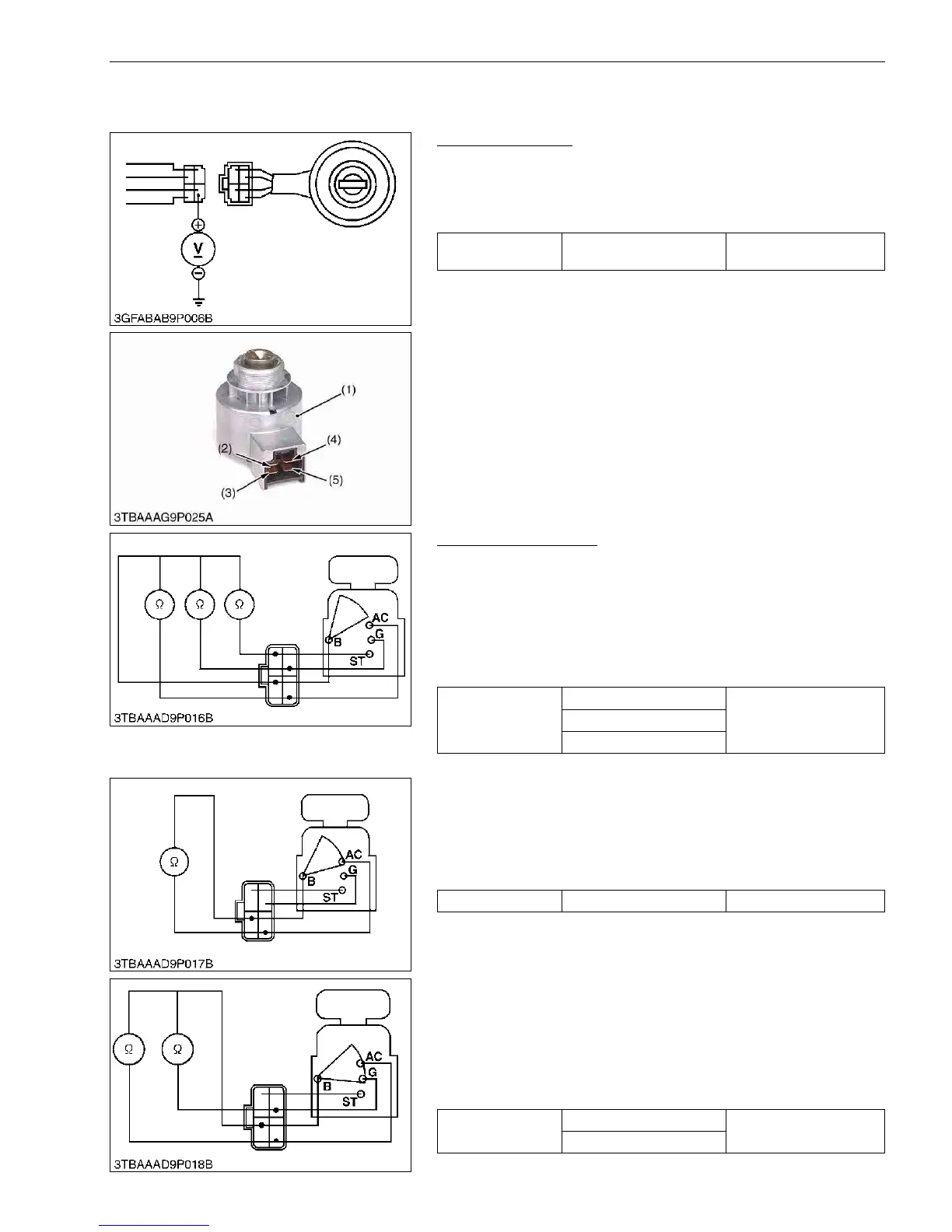
(1) Key Switch
Connector Voltage
1. Measure the voltage with a voltmeter across the connector B
terminal (2) and chassis.
2. If the voltage differs from the battery voltage (11 to 14 V), the
wiring harness is damaged.
9Y1211156ELS0012US0
Key Switch Continuity
1) Key Switch Key at "OFF" Position
1. Set the key switch OFF position.
2. Measure the resistance with an ohmmeter across the B terminal
and the AC terminal, B terminal and ST terminal, B terminal and
G terminal.
3. If infinity is not indicated, the contacts of the key switch are
damaged.
9Y1211156ELS0013US0
2) Key Switch Key at "ON" Position
1. Set the key switch ON position.
2. Measure the resistance with an ohmmeter across the B terminal
and the AC terminal.
3. If 0 Ω is not indicated, the B - AC contact of the key switch are
damaged.
9Y1211156ELS0014US0
3) Key Switch Key at "PREHEAT" Position
1. Set and hold the key switch key at the PREHEAT position.
2. Measure the resistance with an ohmmeter across the B terminal
and the G terminal, and measure the resistance across the B
terminal and the AC terminal.
3. If 0 Ω is not indicated, these contacts of the key switch are
damaged.
9Y1211156ELS0015US0
Voltage
Connector B terminal –
Chassis
Approx. battery voltage
(1) Key Switch
(2) B Terminal
(3) AC Terminal
(4) ST Terminal
(5) G Terminal
Resistance
B terminal – AC terminal
InfinityB terminal – ST terminal
B terminal – G terminal
Resistance B terminal – AC terminal 0 Ω
Resistance
B terminal – G terminal
0 Ω
B terminal – AC terminal
 Loading...