ENGINE
B2301, B2601, WSM
1-S24
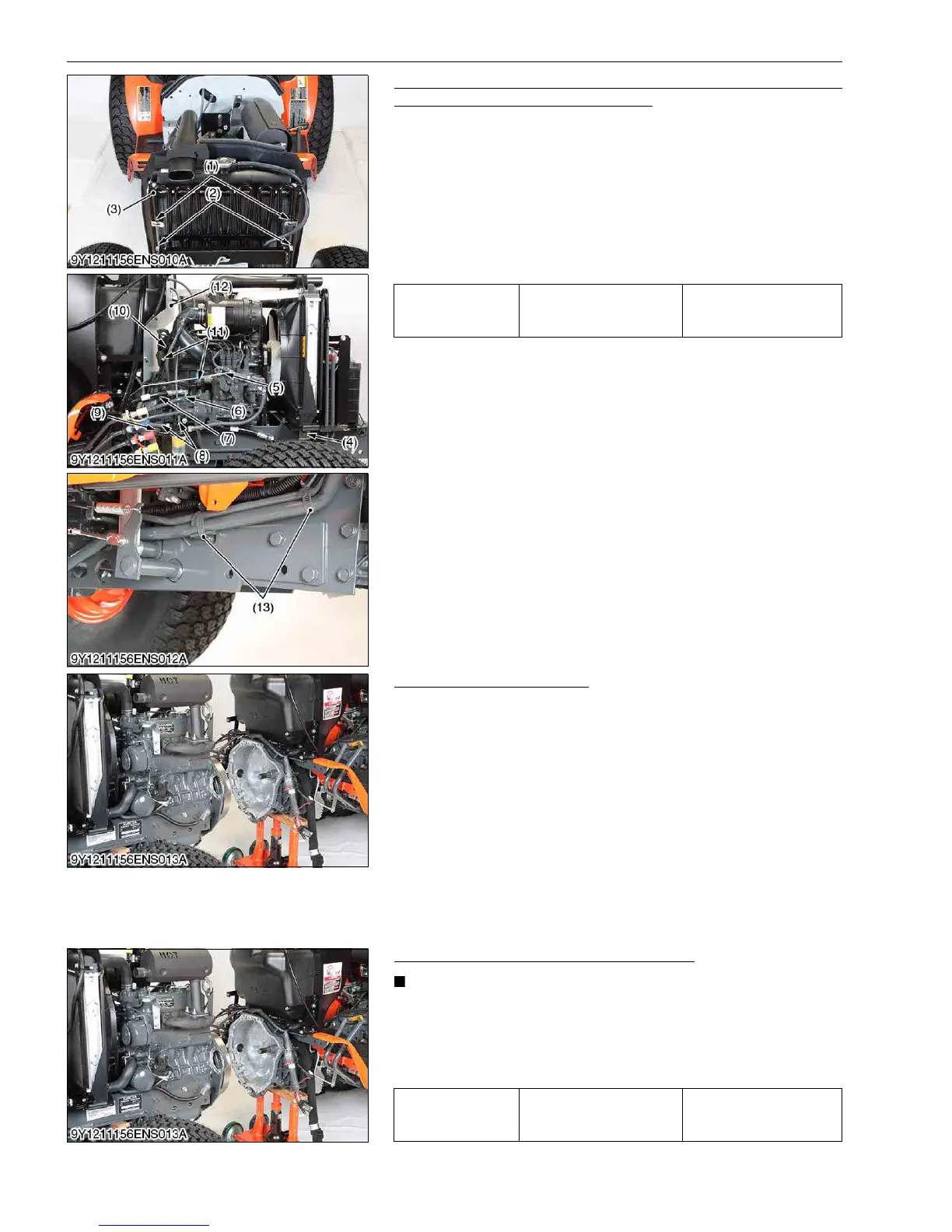
Accelerator Rod, Power Steering Hose, Fuel Hoses,
Connectors and Others (Right Side)
1. Remove the spring plates (1), oil cooler mounting bolts (2) and
oil cooler (3).
2. Remove the clamp (4) and the accelerator rod (5).
3. Disconnect the power steering hose (7), hydraulic delivery pipe
(6) and hydraulic inlet hose (9).
4. Disconnect the fuel hoses (8).
5. Disconnect the connectors (11) and glow plug harness (10).
6. Remove the shuttle plate (12).
7. Disconnect the clamp (13).
9Y1211156ENS0029US0
Separating Clutch Housing
1. Support the transmission with a disassembling stand.
2. Hook the engine with a hoist.
3. Remove the docking bolts and nuts between the engine and the
front case.
(When reassembling)
• Align the spline between the front wheel drive shaft and the
coupling securely.
• Tighten the docking bolts between the engine and the front case
securely.
• Apply liquid gasket (Three Bond 1206D or equivalent) to the
joint face of the engine and the front case.
9Y1211156ENS0030US0
(3) Separating Engine from Front Axle Frame
Separating Engine from Front Axle Frame
• When you replace the engine with new one, please record
the serial number of new engine and the parts number
which is incorporate with its new engine.
1. Remove the engine and front axle frame mounting screw and
separate the engine from the front axle frame.
9Y1211156ENS0031US0
Tightening torque Power steering hose 2
24 to 28 N·m
2.5 to 2.8 kgf·m
18 to 20 lbf·ft
(1) Spring Plate
(2) Bolt
(3) Oil Cooler
(4) Clamp
(5) Accelerator Rod
(6) Hydraulic Delivery Pipe
(7) Power Steering Hose
(8) Fuel Hose
(9) Hydraulic Inlet Hose
(10) Glow Plug Harness
(11) Connector
(12) Shuttle Plate
(13) Clamp
Tightening torque Engine mounting screw
59 to 69 N·m
6.1 to 7.0 kgf·m
44 to 50 lbf·ft

 Loading...