HYDRAULIC SYSTEM
B2301, B2601, WSM
7-S15
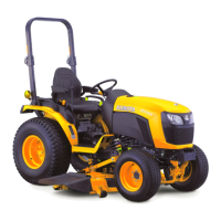
Disassembling Position Control Valve
1. After removing the control valve, disassemble the component
parts as shown in the picture.
(When reassembling)
• Readjust the length "L" of the adjusting bolt.
(Reference)
• Length "L": approximately 10.70 mm (0.4213 in.)
9Y1211156HYS0022US0
(5) Front Loader Control Valve Assembly (If Equipped)
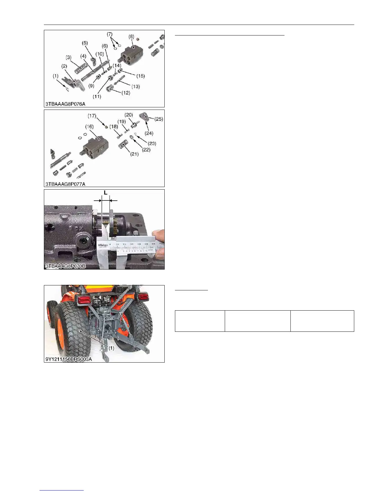
Rear Wheel
1. Place the disassembling stand under the transmission case.
2. Remove the rear wheel (1).
9Y1211156BRS0006US0
(1) External Cir-clip
(2) Lever
(3) Spring
(4) Spool
(5) Spring Holder
(6) Poppet
(7) O-ring
(8) Control Valve Body
(9) Plug
(10) Spring
(11) Unload Plug
(12) Plug
(13) Poppet
(14) Spring
(15) Unload Poppet
(16) Control Valve Body
(17) Nut
(18) Poppet
(19) Spring
(20) Plug
(21) Spring
(22) Spring Holder
(23) External Cir-clip
(24) Adjusting Bolt
(25) Connecting Plate
L: Length of adjusting bolt
Tightening torque
Rear wheel mounting nut
and screw
145 to 150 N·m
14.8 to 15.2 kgf·m
107 to 110 lbf·ft
(1) Rear Wheel

 Loading...