HYDRAULIC SYSTEM
B2301, B2601, WSM
7-M3
3. HYDRAULIC CIRCUIT
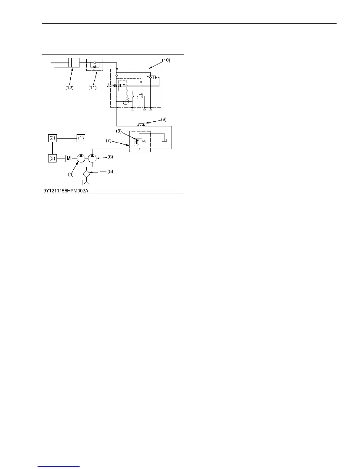
[1] HYDRAULIC CIRCUIT
Two hydraulic pumps (4), (6) are installed in this
series of machines.
Hydraulic oil is forced from hydraulic pump (6) to the
loader control valve (7), relief valve (8), hydraulic outlet
(9) and position control valve (10).
Three point hydraulic oil pressure is controlled by the
relief valve (8).
9Y1211156HYM0003US0
(1) Power Steering Controller
(2) Independent PTO
(3) HST
(4) Hydraulic Pump (for Power
Steering, Independent PTO
and HST)
(5) Oil Filter Cartridge
(6) Hydraulic Pump (for 3-Points
Hitch)
(7) Front Loader Control Valve
(8) Relief Valve
(9) Hydraulic Outlet
(10) Position Control Valve
(11) Lowering Speed Adjusting
Valve
(12) Hydraulic Cylinder

 Loading...