ELECTRICAL SYSTEM
B2301, B2601, WSM
8-S16
Magnetic Switch Test
1. Disconnect the battery negative cable from the battery.
2. Disconnect the battery positive cable and the leads from the
starter B terminal.
3. Remove the starter from the engine.
4. Disconnect the connecting lead (3) from the starter C terminal
(2).
5. Connect a jumper lead from the starter S terminal (2) to the
battery positive terminal post.
6. Connect a jumper lead momentarily between the starter C
terminal (2) and the battery negative terminal post.
7. If the pinion gear does not pop out, check the magnetic switch.
• This test should take no longer than 3 to 5 seconds at a
time.
9Y1211156ELS0022US0
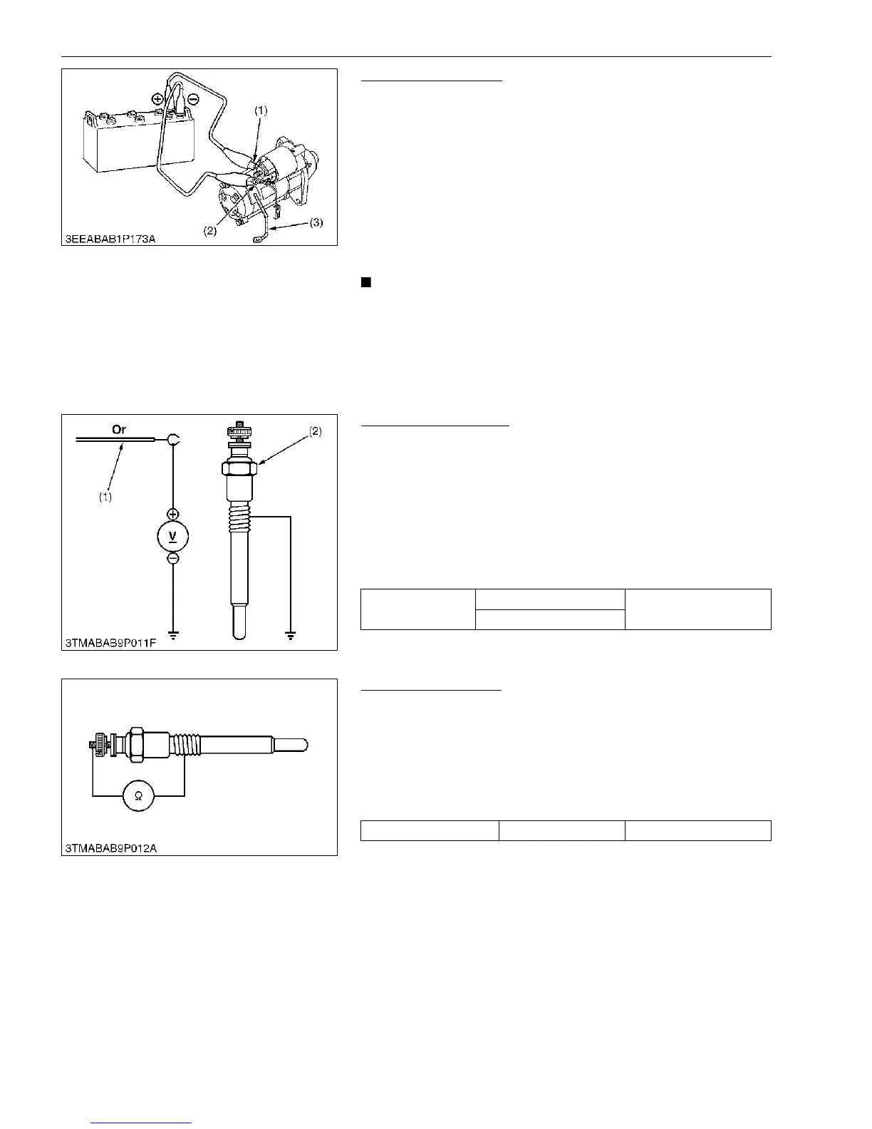
(6) Glow Plug
Lead Terminal Voltage
1. Disconnect the wiring lead (1) from the glow plug (2) after
turning the key switch OFF.
2. Turn the key switch to the PREHEAT position, and measure the
voltage between the lead terminal and the chassis.
3. Turn the key switch to the START position, and measure the
voltage with a voltmeter between the lead terminal and the
chassis.
4. If the voltage at either position differs from the battery voltage,
the wiring harness or key switch is damaged.
9Y1211156ELS0023US0
Glow Plug Continuity
1. Disconnect the leads from the glow plugs.
2. Measure the resistance with an ohmmeter between the glow
plug terminal and chassis.
3. If 0 Ω is indicated, the screw at the tip of the glow plug and the
housing are short-circuited.
4. If the factory specification is not indicated, the glow plug is
damaged.
9Y1211156ELS0024US0
(1) S Terminal
(2) C Terminal
(3) Connecting Lead
Voltage (Lead
terminal - Chassis)
Key switch at PREHEAT
Approx. battery voltage
Key switch at START
(1) Wiring Lead (2) Glow Plug
Glow plug resistance Factory specification Approx. 0.9 Ω

 Loading...