Parker Hannifin
Appendix A SSI Encoders 111
Timing
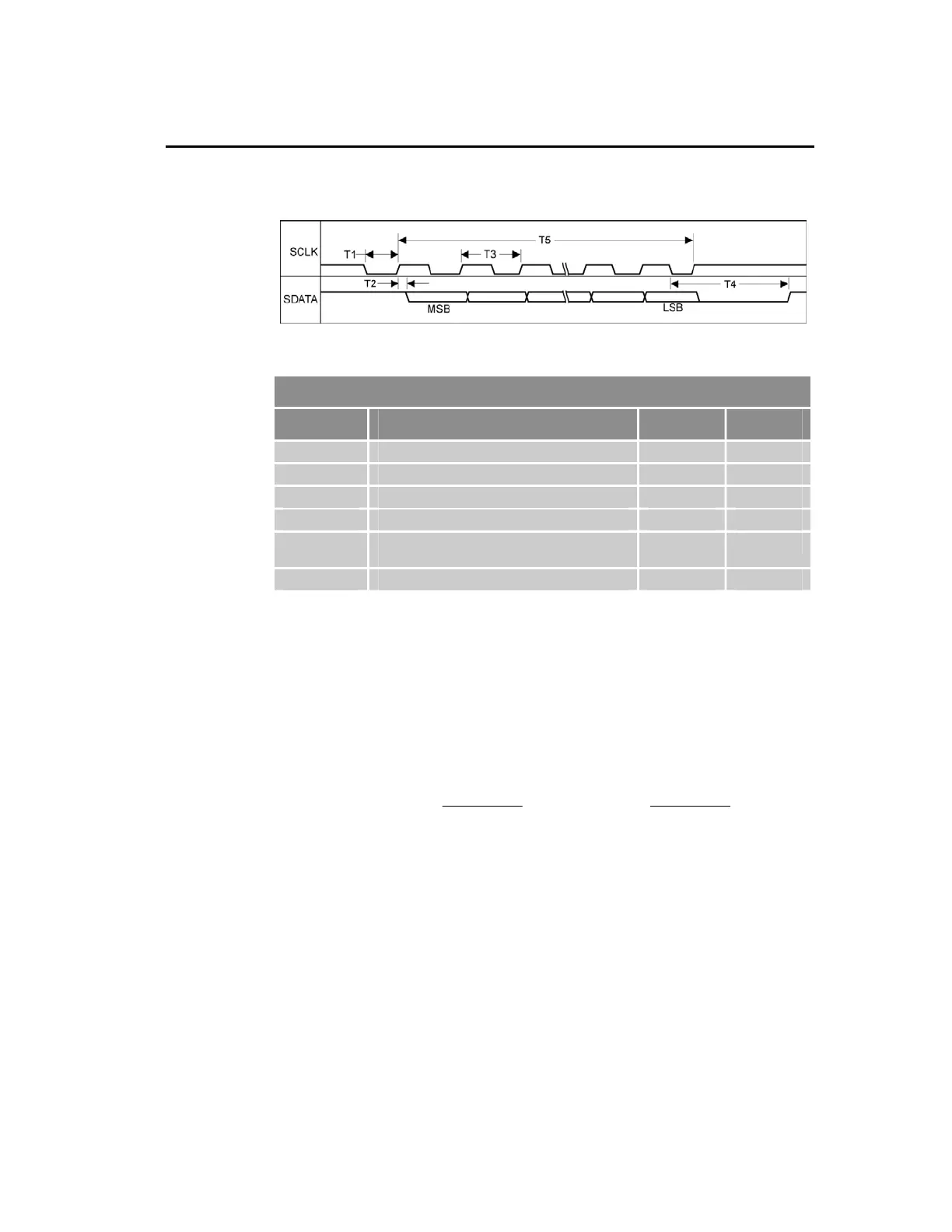
This section describes the SSI transfer cycle timing for the ACR9000 and
ACR9030 controllers. Figure 33 illustrates the cycle timing and Table 64
contains the timing data.
Figure 33 SSI Transfer-Cycle Timing
SSI Transfer-Cycle Timing Data
Symbol Description Min Max
T1 SCLK falling edge to first rising edge 0.5 x T3 --
-- Data setup time before SCLK rising edge 80 ns --
T2 Data hold time after SCLK rising edge 0 --
T3 Programmable SCLK period 641 ns 10.2 µs
T4 Re-transmission timeout period is specified
by slave device
-- --
T5 The number of data bits times SCLK period 641 ns 327.9 µs
Table 64 SSI Transfer-Cycle Timing Data
For example, if:
• Device data word size equals 25-bits
• SSI clock rate equals 781.2 KHz
• Device parameter for T4 equals 20 µs
Then total transfer time equals:
s
μμ
53.28 )
KHz2.781
1
(25 s 20 )
KHz2.781
1
(0.5 T5 T4 T1 =×++×=++
When selecting the SSI clock rate, the total transfer time cannot exceed one
servo period. If it does, the following error(s) may occur:
• SSI encoder values may never change, since the re-transmission
time-out period never expires.
• Data is corrupted because the SCLK is being re-synced at the
beginning of each servo period. The SCLK is re-synced to minimize
jitter.
www.comoso.com

 Loading...


