Parker Hannifin
Compax3 Drives
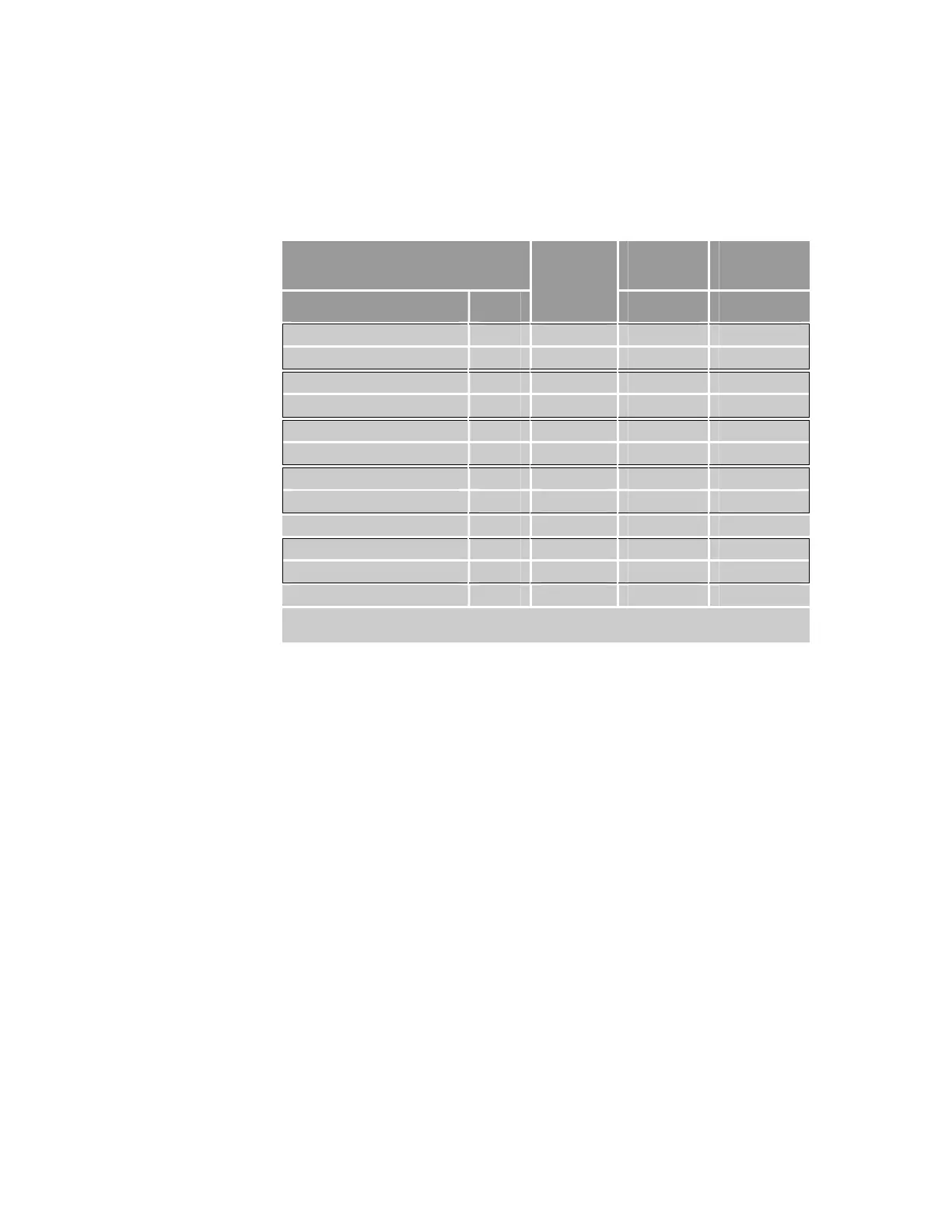
The following pinout is for the Compax3 drive connectors.
Part number ......................................................... 71-021108-xx
Note: A box surrounding pins indicates a requirement for twisted-pair
wiring.
ACR9000 and ACR9030
Controller
Compax3
X11
Compax3
X12
Signal Pin
Wire
Color
Pin Pin
Encoder CHA+ 3 Black 7 —
Encoder CHA−
4 Red 6 —
Encoder CHB+ 5 Green 8 —
Encoder CHB−
6 White 12 —
Encoder CHZ+ 7 Yellow 14 —
Encoder CHZ−
8 Orange 13 —
Drive AOUT+ 14 Blue 9 —
Drive AOUT−
15 Violet 11 —
Drive Fault+ 16 Gray — 2
Drive Enable– 20 Brown — 6 & 8
Drive Enable+ 21 Blue — 1, 7, & 11
Drive GND 24 Violet — 15
NOTE: In the controller connector, pins 17 & 19 are jumpered.
In the Compax3 X12 connector, pins 1, 7, & 11 are jumpered.
Table 41 Connection to Compax3 Pinout
78 ACR9000 Series Hardware Installation Guide
www.comoso.com

 Loading...


