Parker Hannifin
Parker Stepper Drives: E-AC, E-DC, Zeta, etc.
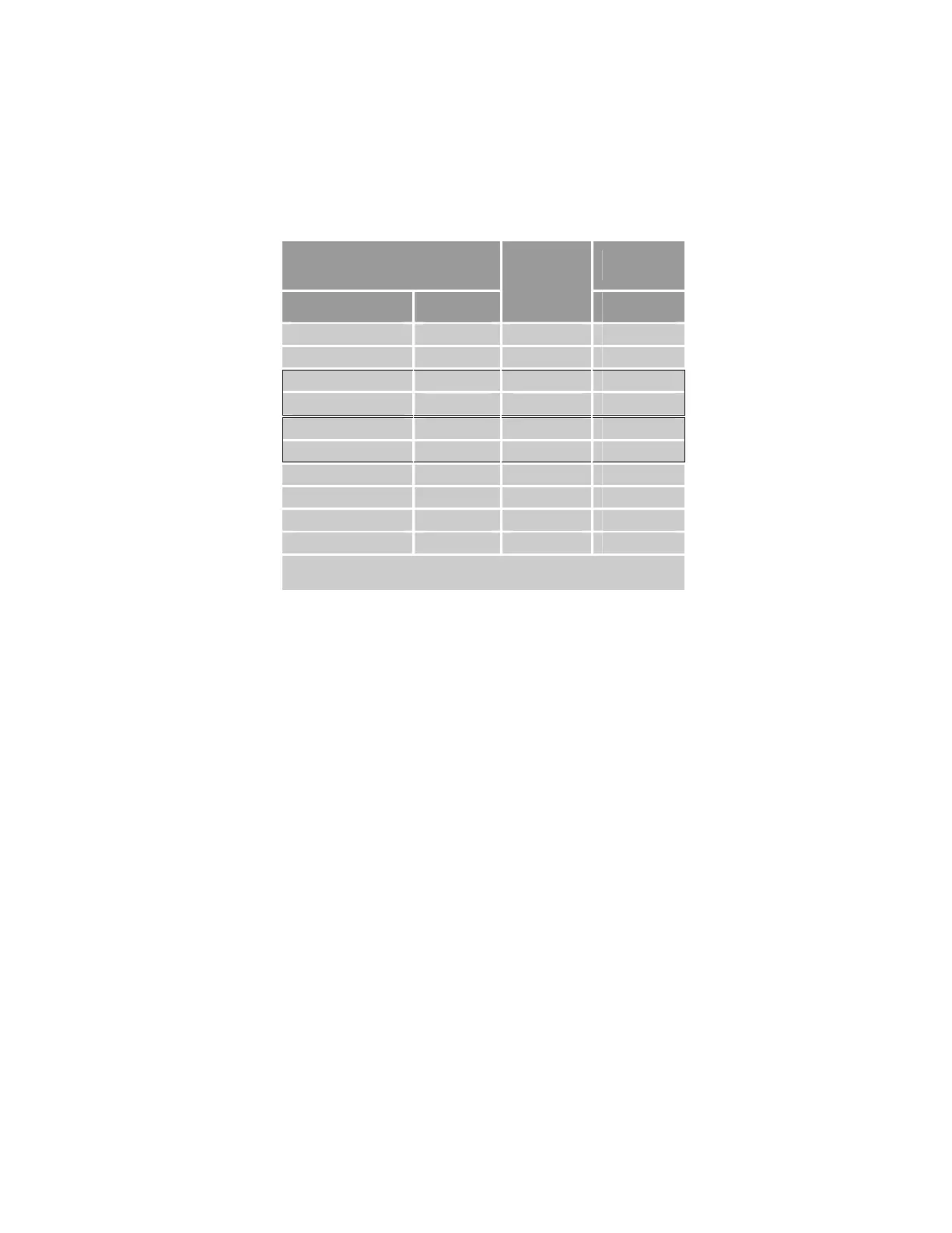
The following pinout is for all Parker Stepper drive Indexer connectors.
Part number ......................................................... 71-021113-xx
Note: A box surrounding pins indicates a requirement for twisted-pair
wiring.
ACR9000 and ACR9030
Controller
Stepper
Signal Pin
Wire
Color
Pin
DC RETURN 2 Yellow 21
5 VDC PWR 9 Orange 11
Drive Step+ 10 Black 1
Drive Step−
11 Red 14
Drive Direction+ 12 Green 2
Drive Direction– 13 White 15
Drive Fault+ 17 Blue 9
5 VDC PWR 18 Violet 16
Drive Enable+ 21 Gray 17
Drive Reset+ 23 Brown 23
Note: In the controller connector, the following pins are jumpered:
19 & 20, 1 & 16, 22 & 24
Table 45 Connection to Parker Stepper Pinout
82 ACR9000 Series Hardware Installation Guide
www.comoso.com

 Loading...


