Parker Hannifin
Procedure 2—Hall Wires
Use this procedure to connect your Hall wires to the drive.
1. First operate the drive in
DMODE1 and verify that the motor turns
clockwise. If not, swap any two motor wires.
2. Remove the motor power leads, leaving the feedback cable connected
to the drive. Connect motor power wires U and V and slowly apply a
positive voltage with respect to W. (See Figure 49.)
Note: A variable low voltage (5-24V) current limiting (less than
continuous current rating of motor) power supply is preferred.
Warning — This procedure could damage the motor. Slowly increase the
voltage until the motor moves. Do not exceed the rated current.
Safety Warning — High-performance motion control equipment is capable
of producing rapid movement and very high forces. Unexpected motion may
occur especially during the development of controller programs.
KEEP
WELL CLEAR
of any machinery driven by stepper or servo motors. Never
touch any part of the equipment while it is in operation.
3. If
THALL reports a value of 1, 2 or 4, change SHALL from either 0 to 1
or from 1 to 0. After you change
SHALL, reset the drive.
4. Change the Hall wires until
THALL reports a value of 6.
5. Connect motor wires U and W and slowly apply a positive voltage with
respect to V.
6. If
THALL does not report a value of 3, change Hall wires B and C.
If
THALL reports a value of 3, the wires are connected correctly.
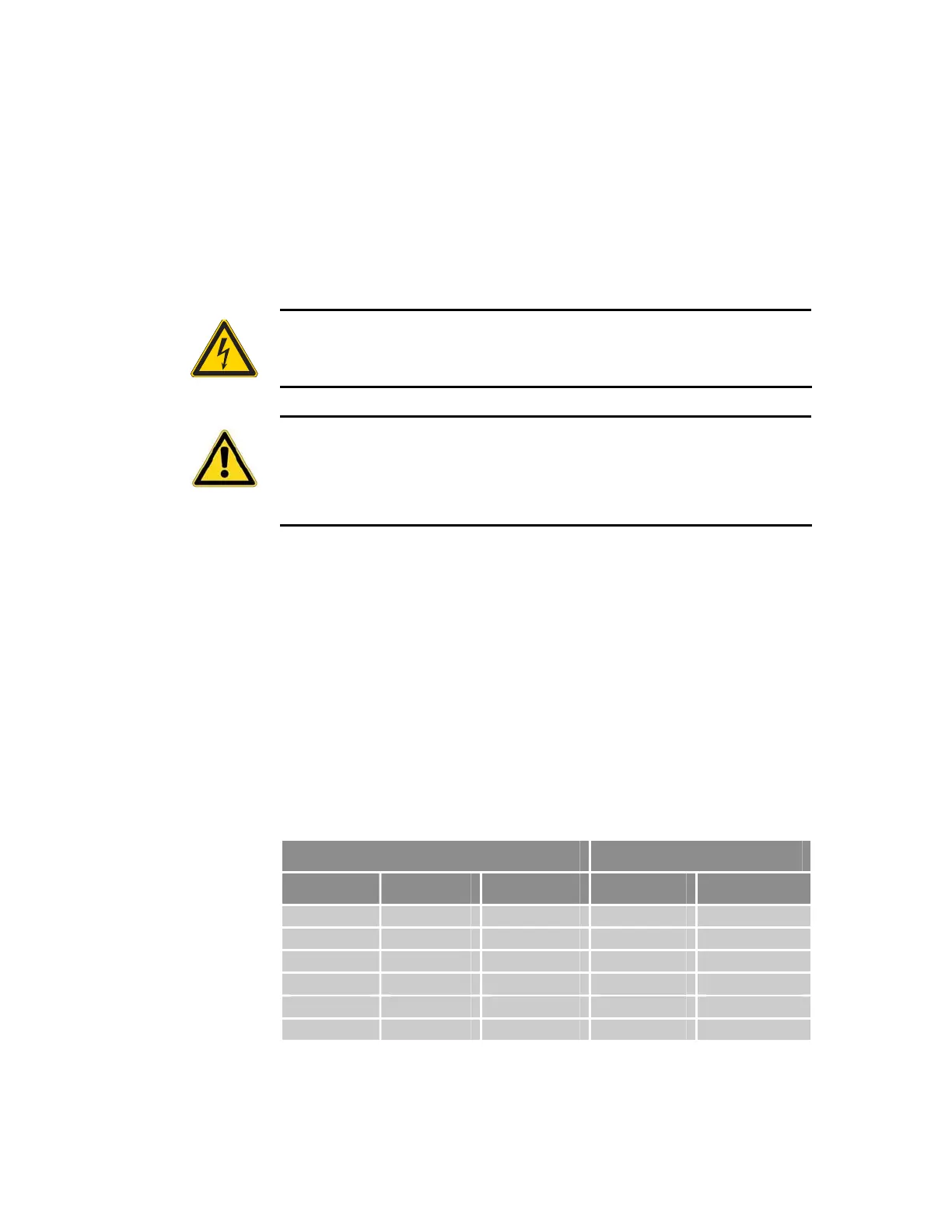
Table 85 on page 193 summarizes phase voltages and their corresponding
Hall states. Starting with
SHALLØ and the phase voltages as shown, the
THALL command should report the Hall states that match the “Correct”
column. If instead
THALL reports Hall states that match the “Use SHALL1”
column, enter
SHALL1 and reset the drive. The Hall states should now
match the “Correct” column. For more information, see Figure 50 on page
194.
Phase Hall State
U V W Correct
Use SHALL1
– – + 1 6
– + + 5 2
– + – 4 3
+ + – 6 1
+ – – 2 5
+ – + 3 4
Table 85 Configuring Hall Sensors
Appendix H ETHERNET Powerlink 193
www.comoso.com

 Loading...


